EasyManua.ls Logo

Akai GX-F31 Service Manual

Akai GX-F31
133 pages
To Next Page IconTo Next Page
Page #1 background imageLoading...
Page #1 background image
AKAi
SERUl[E
fflADUAl
i:::::::l
.....,..,,
"'
""
'
"•
"''
. '
'"'
...
-
D
c::=
1r-
··
.-
··
,-
..
"· - ··· - -.
••
••
..
...
-•·• - ··
◄◄
I
..
.
_··©)~-~:g1;fg~-:@
••
~:-
,
·:·:
·
JY.Jlll
~•
~~-
O
~H
..
u
._
..
..,.11:.,.•o
i::A
..
CT
T
O!I
.1:
::
u
1:
C><
,.,aa
Ox
•FS
I
[llj-•
·••
STEREO CASSETTE DECK
MODEL
GX-f
31
MODEL
GX-F51
MODEL
GX-F71
Question and Answer IconNeed help?

Do you have a question about the Akai GX-F31 and is the answer not in the manual?

Akai GX-F31 Specifications

General IconGeneral
BrandAkai
ModelGX-F31
CategoryCassette Player
LanguageEnglish

Summary

AKAI Service Manual

Stereo Cassette Deck Models

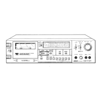
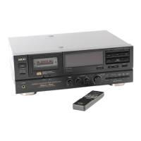
Identifies the GX-F31, GX-F51, and GX-F71 models covered.

Section 3 Service Manual Model GX-F51

SAFETY INSTRUCTIONS

SAFETY CHECK AFTER SERVICING

Guidelines for ensuring safety after service procedures are completed.

PRECAUTIONS DURING SERVICING

Essential precautions to be taken before and during servicing.

SECTION 1 CIRCUIT OPERATION DESCRIPTION

I. DESCRIPTION OF GX-F71 AUTO TUNING FUNCTION

Explains the auto-tuning functionality for the GX-F71 model.

II. GX-F71 SYSCON CIRCUIT FUNCTIONS

Details the functions of the SYSCON circuit in the GX-F71.

III. DESCRIPTION OF GX-F51 CIRCUIT

Outlines the circuit operation for the GX-F51 model.

IV. AUTO FADER CIRCUIT

Describes the operation of the auto-fader circuit.

V. CAM MOTOR DRIVE CIRCUIT

Explains the function of the cam motor drive circuit.

VI. REEL MOTOR DRIVE CIRCUIT

Details the operation of the reel motor drive circuit.

2. MEANING EACH TERMINAL OF CPU (LM6402 H063)

PIN NO., SYMBOL, MEANING

Table listing pin numbers, symbols, and their meanings for the CPU.

SECTION 2 SERVICE MANUAL MODEL GX-F31

I. SPECIFICATIONS

TRACK SYSTEM, TAPE, TAPE SPEED, HEADS, MOTORS, WOW & FLUTTER

Details core mechanical and head specifications.

FREQUENCY RESPONSE, FREQUENCY RANGE, SIGNAL TO NOISE RATIO

Covers audio performance specifications.

HARMONIC DISTORTION, INPUT, OUTPUT, DIN

Provides audio input/output and distortion specifications.

V. MECHANICAL ADJUSTMENT

TAPE SPEED ADJUSTMENT

Outlines the process for adjusting tape speed.

POTENTIOMETER PRESET VOLTAGE ADJUSTMENT

VI. HEAD ADJUSTMENT

VII. AMPLIFIER ADJUSTMENT

Amplifier Adjustment Steps

PB EQ AMP ADJUSTMENT

Procedures for adjusting the PB EQ amplifier.

DOLBY ENCODER ADJUSTMENT

Adjustments for Dolby C-type encoder level and MPX filter.

DOLBY DECODER ADJUSTMENT

Adjustments for Dolby B/C type decoder levels.

SECTION 3 SERVICE MANUAL MODEL GX-F51

II. CONTROLS

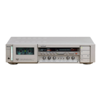
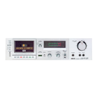
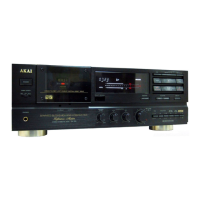
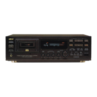
Describes the controls and functions of the GX-F51 unit.

III. PRINCIPAL PARTS LOCATION

Shows the physical location of main components within the unit.

V. MECHANICAL ADJUSTMENT

Outlines procedures for mechanical adjustments on the unit.

VI. HEAD ADJUSTMENT

Details the steps for adjusting the audio heads for optimal performance.

VII. AMPLIFIER ADJUSTMENT

Describes amplifier calibration and adjustment procedures.

VIII. TUNING CIRCUIT ADJUSTMENT

Covers adjustments for the tuning circuit section.

VIII. TUNING CIRCUIT ADJUSTMENT

SECTION 4 SERVICE MANUAL MODEL GX-F71

I. SPECIFICATIONS

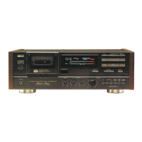
Details the technical specifications of the GX-F71 model.

II. DISMANTLING OF UNIT

Step-by-step instructions for disassembling the unit.

VI. MECHANICAL ADJUSTMENT

Outlines procedures for mechanical adjustments on the unit.

VII. HEAD ADJUSTMENT

Details the steps for adjusting the audio heads for optimal performance.

VIII. AMPLIFIER ADJUSTMENT

Describes amplifier calibration and adjustment procedures.

II. DISMANTLING OF UNIT

VI. MECHANICAL ADJUSTMENT

PINCH ROLLER PRESSURE MEASUREMENT

Details how to measure and set pinch roller pressure.

TAPE SPEED ADJUSTMENT

VII. HEAD ADJUSTMENT

Head Adjustment Procedures

REC/PB HEAD PROJECTION ADJUSTMENT

Procedure for setting the projection of the REC/PB head.

REC/PB HEAD HEIGHT ADJUSTMENT

Procedure for setting the height of the REC/PB head.

REC/PB HEAD AZIMUTH ALIGNMENT ADJUSTMENT

Steps to align the azimuth of the REC/PB head.

VIII. AMPLIFIER ADJUSTMENT

Tuning P.C Board Adjustments

Tuning Circuit Adjustment Steps

REC BIAS OSC ADJUSTMENT

Adjusting the REC BIAS OSC frequency.

FREQUENCY RESPONSE ADJUSTMENT

Adjusting frequency response for different tape types.

RECORDING LEVEL ADJUSTMENT

Adjusting recording level.

I. MODEL GX-F31 RECOMMENDED SPARE PARTS

3. PRE AMP P.C BOARD BLOCK

4. SYS. CON. P.C BOARD BLOCK

TUNING P.C BOARD

Lists parts for the TUNING P.C Board.

III. MODEL GX-F71 RECOMMENDED SPARE PARTS

1. MODEL GX-F31 RECOMMENDED SPARE PARTS

Recommended Spare Parts List

A list of recommended spare parts for the GX-F31 model.

SECTION 6 SCHEMATIC DIAGRAM

SCHEMATIC DIAGRAM OF ICs

Schematic diagrams for integrated circuits used in the unit.

GX-F31 POWER & SYSCON SCHEMATIC DIAGRAM

Schematic for GX-F31 power and SYSCON circuits.

GX-F31 AMP SCHEMATIC DIAGRAM

Schematic for GX-F31 amplifier circuits.

GX-F51 POWER & SYSCON SCHEMATIC DIAGRAM

Schematic for GX-F51 power and SYSCON circuits.

GX-F51 AMP SCHEMATIC DIAGRAM

Schematic for GX-F51 amplifier circuits.

GX-F51 TUNING SCHEMATIC DIAGRAM

Schematic for GX-F51 tuning circuits.

GX-F71 POWER & SYSCON SCHEMATIC DIAGRAM

Schematic for GX-F71 power and SYSCON circuits.

GX-F71 AMP SCHEMATIC DIAGRAM

Schematic for GX-F71 amplifier circuits.

GX-F71 TUNING SCHEMATIC DIAGRAM

Schematic for GX-F71 tuning circuits.

IC Block Diagrams

GX-F31 Power Supply & Syscon Schematic Diagram

GX-F31 Amplifier Schematic Diagram

GX-F51 Power Supply & Syscon Schematic Diagram

GX-F51 Amplifier Schematic Diagram

GX-F51 Tuning Schematic Diagram

GX-F71 Power & Syscon Schematic Diagram

GX-F71 Amplifier Schematic Diagram

GX-F71 Tuning Schematic Diagram

Related product manuals