VIII.
TUNING
CIRCUIT
ADJUSTMENT
I)
Standard Signal
(I
kHz)
output
Adjustment
a. Set
to
REC/PAUSE.
b. Apply
+SY
DC
to
TP3
of
the Pre Amp
PCB.
c.
Input square
wave
of
3Vp-p or more, 1057 ±
10
Hz, into
TP-1
of
the tuning
PCB.
d. Adjust VR3
of
the tuning
PCB
so that the level
of
TP4
of
Pre Amp
PCB
will
be
-25.5
± 0.1 dBm.
2)
Standard Signal (IO kHz) Output Adjustment
a.
Set to REC/PAUSE.
b. Apply
+SV
DC
to
TP3
of
Pre Amp
PCB.
c. Input square
wave
of
3Vp-p
or
more, 9941 ± 100
Hz, into TP2
of
the tuning
PCB.
d. Adjust VR4
of
the tuning
PCB
so
that the
level
of
TP4
of
Pre Amp
PCB
will
be
-24.0
± 0.1 dBm.
3)
A/D
Converter Analogue Level Adjustment
a. Set to PLAY mode without inserting a tape.
3-8
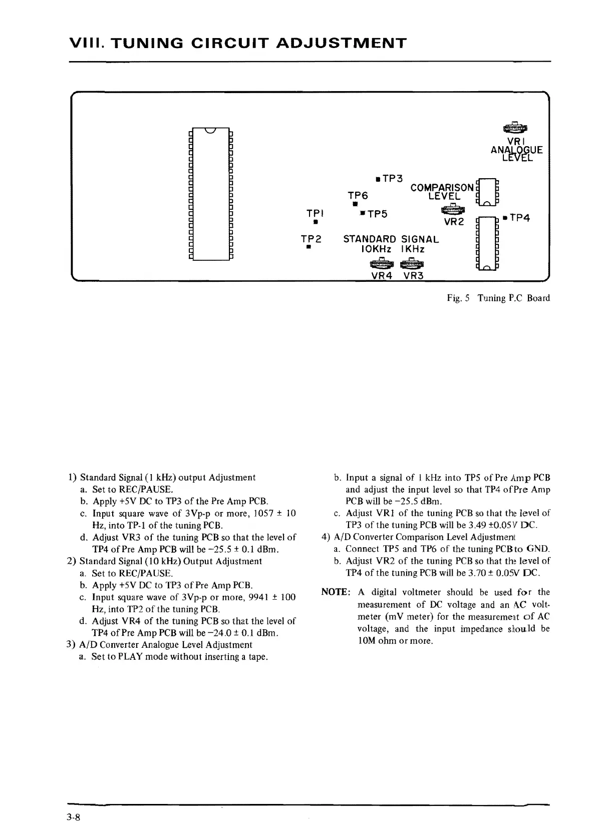
■
TP3
0
COMPARISON
TP6
LEVEL
TPI
•
•TP5
~~
D
■
TP4
•
TP2
•
STANDARD
SIGNAL
IOKHz
IKHz
~
@I
VR4
VR3
Fig.
5 Tuning
P.C
Board
b.
Input a signal
of
I
kHz
into
TPS
of
Pre Amp
PCB
and adjust the input level
so
that
TP4
of
Pre
Amp
PCB
will
be
-25.5
dBm.
c.
Adjust VRI
of
the tuning
PCB
so
that
the
level
of
TP3
of
the tuning
PCB
will
be 3.49 ±0.0SV DC.
4) A/D Converter Comparison Level Adjustment
a.
Connect
TPS
and TP6
of
the tuning
PCB
to
GND.
b.
Adjust VR2
of
the tuning
PCB
so
that
the
level
of
TP4
of
the tuning
PCB
will be 3.70 ± 0.0SV DC.
NOTE:
A digital voltmeter should
be
used
for
the
measurement
of
DC
voltage and an
A.C
volt-
meter (mV meter) for the measurement
of
AC
voltage, and the input impedance sliou.ld
be
lOM
ohm
or
more.
 Loading...