Do you have a question about the Akai GX-F25 and is the answer not in the manual?
Detailed specifications for the cassette deck.
Step-by-step instructions for disassembling the unit.
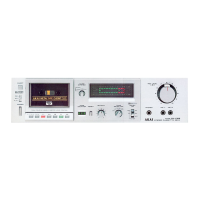
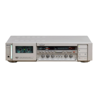
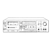
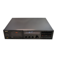
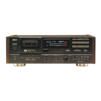
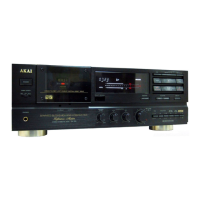
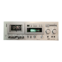
Identification and function of all front and rear panel controls.
Diagrams showing the location of major internal components.
Procedures for changing voltage and cycle settings.
Steps for converting the unit's voltage.
Note on cycle conversion for DC motors.
Adjustments related to tape transport and mechanical parts.
Adjusting flywheel for play stability.
Adjusting play and brake plunger positions.
Measuring pinch roller pressure.
Measuring take-up, back tension, and FF/RWD torque.
Adjusting tape speed using a test tape.
Procedures for aligning and adjusting the playback and record heads.
Adjusting tape guide height for smooth tape travel.
Adjusting head height for optimal output.
Aligning head azimuth for channel balance.
Procedures for calibrating electronic circuits and levels.
Adjusting playback level.
Adjusting playback equalization.
Adjusting recording peaking.
Adjusting frequency response for LN tape.
Table listing DC resistance values for specific coils.
List of printed circuit boards and their identification numbers.
List of PC boards and their part numbers.
Diagrams showing the layout of various PC boards.
Schematic for Power Supply and Lamp PCBs.
Schematic for Power Supply and Lamp PCBs.
Schematic for Power Supply and Lamp PCBs.
Schematic for Power Supply and Lamp PCBs.
Schematic for Power Supply and Lamp PCBs.
List of recommended spare parts for repairs.
Exploded view and parts for the reel table assembly.
Exploded view and parts for the mecha assembly.
Exploded view and parts for the pre-amp PCB.
Exploded view and parts for power supply PCBs.
Exploded view and parts for system control PCB.
Exploded view and parts for general assembly.
Exploded view and parts for final assembly.
Diagram showing AC inlet types and cord connections.
Table of AC cord sets and their part numbers.
Circuit diagrams for specific IC components.
Schematic for the amplifier section of the GX-F25.
Schematic for power supply and system control.
| Type | 2-head, single compact cassette deck |
|---|---|
| Track System | 4-track, 2-channel stereo |
| Tape Speed | 4.76 cm/s |
| Tape Type | type I, CrO2, Metal |
| Heads | 1 x record/playback, 1 x erase |
| Motor | DC servo motor |
| Inputs | Line |
| Outputs | Line |