EasyManua.ls Logo

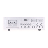
Akai GXC-760D

Akai GXC-760D
8 pages
To Next Page IconTo Next Page
To Previous Page IconTo Previous Page
Loading...
INDEX
COUNTER
AND
RESET
BUTTON
MEMORY
REWIND
BUTTON
It
is
recommended
Tape
indexing
is
made
easy
with
this
3-digit
Index
Counter.
Set
Index
Counter
to
''000"
and
depress
Memory
Rewind
Button.
xe
depressed
prior
Provides
an
easy
reference
for
quickly
locating
positions
on
Automatic
Stop
at
this
setting
can
then
be
effected
from
Rewind.
uring
an
operating
the
tape.
To
reset
to
''000"',
depress
Reset
Button.
LEFT
VU
METER
Indicates
left
channel
recording
and
playback
levels.
PEAK
CHECK
SWITCH
Depressing
this
switch
to
ON
(in)
position
sets
the
VU
Meters
for
quick
response,
enabling
precise
peak
level
check
of
pulsive
input
signals.
*
See
PEAK
CHECK
procedure.
RIGHT
VU
METER
Indicates
right
channel
recording
and
playback
levels.
DOLBY
INDICATOR
LAMP
Lights
when
the
Dolby
NR
Switch
is
depressed.
OUTPUT
LEVEL
CONTROL
For
left/right
line
output
volume
adjustment.
LEFT
MIC/LINE
RECORDING
LEVEL
CONTROLS
Controls
left
channel
recording
input
level.
Adjust
while
observing
left
VU
Meter.
RIGHT
MIC/LINE
RECORDING
LEVEL
CONTROLS
A
Controls
right
channel
recording
input
level.
Adjust
while
observing
right
VU
Meter.
REC
CAL
ADJUSTERS
(left
and
right)
swim
Recording
Calibration
Level
Adjusters
(Refer
to
Dolby
Level
Adjustment
Q
procedure).
Aw
ADREVETES
OO
POWER
SWITCH
HEADPHONE
JACK
Accommodates
stereo
headphones
of
8
ohms
impedance
for
monitoring
or
private
headphone
listening.
MICROPHONE
JACKS
(left
and
right)
600
ohm
impedance
microphones
are
recommended.
CAL
TONE
SWITCH
Activates
a
built-in
oscillator
to
supply
a
400
Hz
recording
signal
for
Recording
Calibration
Adjustment.
(Refer
to
Dolby
Recording
Level
Adjustment
procedure).
*
Keep
at
OFF
position
at
all
other
times.
MPX
FILTER
SWITCH
Prevents
disturbance
caused
by
the
19
KHz
pilot
signal
during
FM
stereo
broadcast
recording
with
the
Dolby
System
through
an
FM
receiver.
*
Keep
at
OFF
position
at
all
other
times.
REMOTE
CONTROL
JACK
Remote
control
of
all
operating
functions
can
be
accomplished
with
optional
accessory
Remote
Control
Unit
RC-17
or
RC-18.
Either
of
these
remote
control
units
can
also
be
used
together
with
a
timer
for
absentee
recording.
(See
TIMER
RECORDING
procedure).
SPOD
AnD
TW
poa
o
sruba
aa
oaae
manes
AKAT
ELLE
RIG
Qe
LED.
LE
LU
EE
lal
lap
umsum
m
LINE
INPUT
JACKS
(left
and
right)
Connects
to
tape
outputs
of
external
source
LINE
OUTPUT
JACKS
(left
and
right)
Connects
to
tape
inputs
of
external
amplifier
or
tape
recorder.

Related product manuals