8
8
In the Pink Box we see the realtime THD. The XLR connects to inputs 1+2 for AUX in
Out XLR so we want to get the best reading for inputs 1+2.
The grey boxes in RED are the test result values, which will display after clicking “Test
Aux in out XLR” or after a full “Test Audio Through” has been done.
Proceed through the next 2 routings in the same way. These will be saved with the
application in the app folder as NC17levels.maxpat . This file may be copied to latter
versions of the app to maintain calibration settings.
Testing Routings
Each routing is tested individually, then cables are moved and switches set for the next
test.
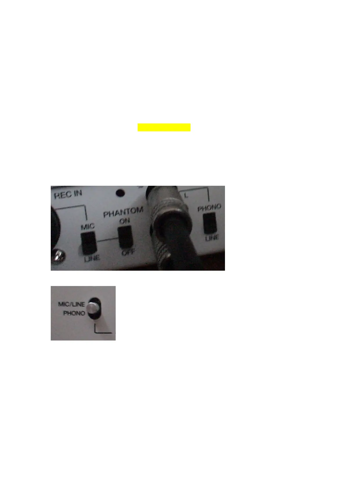
The back switches referred to are pictured here
The top switch referred to is pictured here
Routing 1 – Stereo out to combo Jack with the top set to MIC/LINE and the back set to
MIC
Routing 2 – Stereo out to combo Jack with the top set to MIC/LINE and the back set to
LINE
Routing 3 – Assignable Mix Out to RCA, with the top switch set to PHONO and the back
switch set to PHONO
 Loading...