Front panel
5
F [MAIN OUT] jacks (phone): These are balanced main output jacks for connecting phone plug cables.
They output the same signal as the [MAIN OUT] (XLR) jacks.
G [MIDI IN I]/[MIDI IN II] connectors: These connectors receive MIDI messages. MIDI messages
can be received independently at each connector.
H [MIDI OUT A]–[MIDI OUT D] connectors: These connectors transmit MIDI messages. MIDI mes-
sages can be transmitted independently from each connector A–D.
I [USB] connector (slave): This connector allows the MPC4000 to be connected to a computer (Win-
dows/Macintosh) for file transfer or remote control.
J SCSI connector:
This is a D-sub half-pitch 50-pin (high pitch 50 pin) connector for connecting
SCSI-compatible devices. SCSI-type CD-ROM drives or hard disks can be connected. For details on SCSI
connections and supported devices, contact your Akai dealer or Akai Professional M.I Service Department.
K [FOOT SWITCH 1]/[FOOT SWITCH 2] jacks: Foot switches can be connected to these jacks to per-
form operations such as punch-in/out.
L [SMPTE IN] jack: This jack receives SMPTE time code (LTC) from an external device. Use this when
you want an external device to be the time code master, and the MPC4000 to operate in synchronization
with the external device.
M [SMPTE OUT] jack: This jack transmits SMPTE time code from the MPC4000 to an external device.
Use this when you want the MPC4000 to be the time code master, and an external device to operate in
synchronization with it.
N [DIGITAL IN] jack: This is a coaxial type digital input jack. The digital output jack of a CD player or
DAT can be connected to this.
O [DIGITAL OUT] jack: This is a coaxial type digital output jack. It outputs the same signal as the
[MAIN OUT] jacks.
P [WORDCLOCK IN] jack: This is a BNC jack for receiving a word clock signal from an external
device. Use this when the MPC4000’s digital audio signal processing must be synchronized with that
of an external digital recorder or digital mixer.
Q [TERMINATOR] switch: This is an on/off switch for word clock termination. If a word clock signal is
being supplied from an external device to the MPC4000’s [WORDCLOCK IN] jack, you will normally
set this to the ON position.
R Option slot: This slot allows a separately sold interface card to be installed.
S Power supply connector: Connect the included power cable to this connector.
* You must use the cable that is included with the MPC4000.
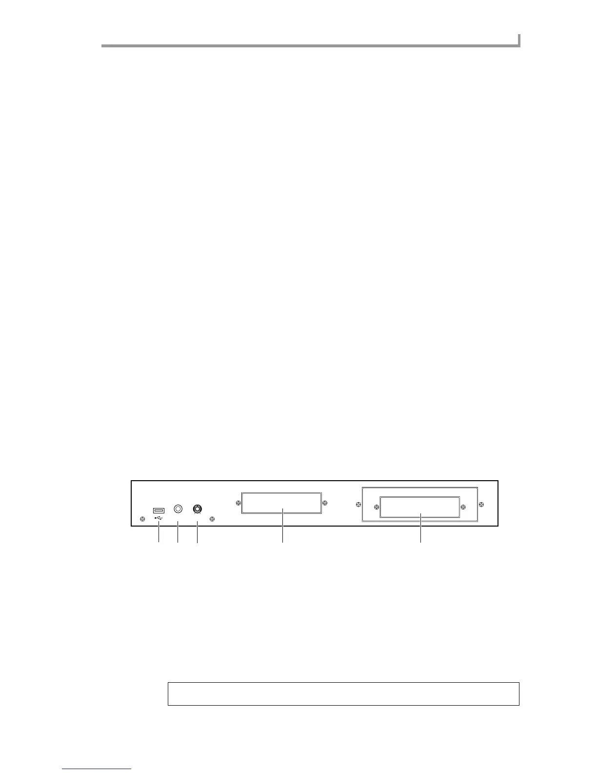
Front panel
A [USB] connector (host): This USB connector allows a USB-type CD-ROM drive, removable drive, or
USB keyboard etc. to be connected. Unlike the rear panel USB connector, this connector cannot be con-
nected to a computer. For details on USB connections and supported devices, contact your Akai dealer
or Akai Professional M.I Service Department.
B [PHONES] jack: This is a stereo phone jack for connecting headphones. It outputs the same signal as
the [MAIN OUT] jacks.
C [PHONES LEVEL] knob: This is a dedicated volume knob for the [PHONES] jack.
D 3.5 inch bay: An ATAPI-type internal hard disk or ZIP drive can be installed in this bay.
E 5 inch bay:
An ATAPI-type CD-ROM drive can be installed in this bay. A 3.5 inch drive can also be installed
here. For compatible devices, contact your Akai dealer or Akai Professional M.I Service Department.
Note: If a removable disk drive is installed in the MPC4000, protect the disk by taking it out of the drive when
you are not actually loading or saving data on it.
PHONES LEVEL
14
3
2
5
 Loading...