SAFETY
INSTRUCTIONS
PRECAUTIONS DURING SERVICING
1. Parts
indentified
by
the
A
(*)
symbols are critical for
safety Replace
only with
parts
number specified.
2. In addition to safety, other parts and assemblies
are
specified forconformance with such regulations as
those applying to spurious radiation.
These must also
be
replaced only with specified re-
placements.
Examples: RF converters, tuner units, antenna selector
switches, RF cables,
noise
blocking capacitors, noise
blocking
filters,
etc.
3.
Use
specified internal wiring
note
especially:
1)
Wires covered with PVC tubing
2)
Double insulated wires
3)
High voltage leads
4.
Use
specified insulating
materials for
hazardous live
parts. Note especially:
1)
Insulation Tape
2)
PVC tubing
3)
Spacers (Insulating Barriers)
4)
Insulation sheets for
transistors
5)
Plastic screws for
fixing microswitch (especially in
turtable)
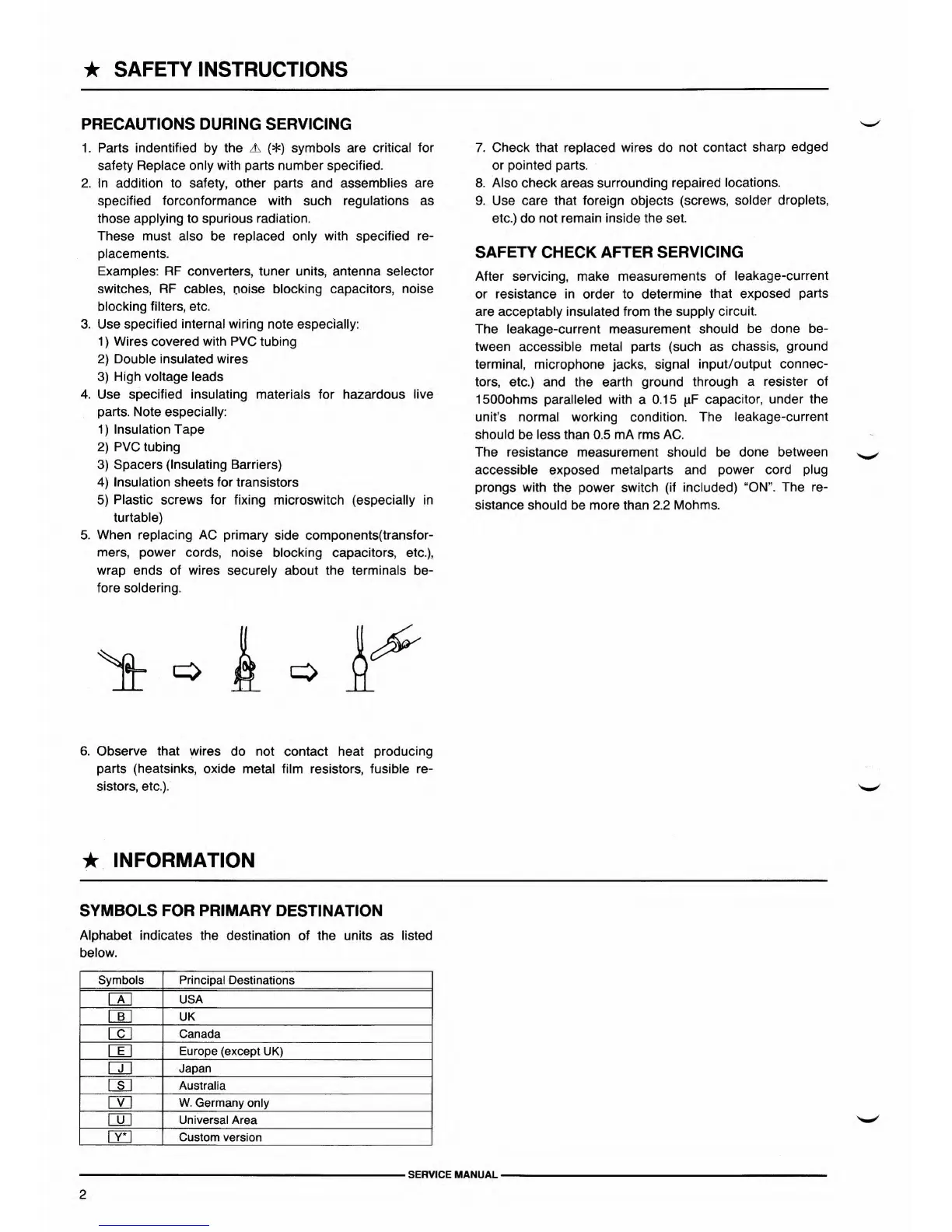
5. When replacing AC
primary side components(transfor-
mers,
power cords, noise blocking capacitors, etc.),
wrap ends of wires securely about the terminals
be-
fore soldering.
6.
Observe that wires
do not contact heat
producing
parts (heatsinks, oxide
metal film resistors, fusible re-
sistors, etc.).
7. Check that
replaced
wires do not
contact sharp edged
or pointed parts.
8. Also check areas surrounding repaired
locations.
9.
Use
care
that
foreign objects (screws,
solder droplets,
etc.) do
not remain inside the set.
SAFETY
CHECK
AFTER SERVICING
After servicing, make
measurements of
leakage-current
or resistance in order to determine
that exposed
parts
are acceptably insulated from the
supply circuit.
The leakage-current measurement
should be
done
be-
tween
accessible metal parts
(such
as
chassis,
ground
terminal, microphone jacks, signal
input/output
connec-
tors, etc.) and the earth ground
through a resister of
1500ohms paralleled with
a 0.15
\if
capacitor, under the
unit’s normal working condition. The
leakage-current
should be less than 0.5 mA rms AC.
The resistance measurement should be
done between
accessible exposed metalparts and
power cord plug
prongs with the
power
switch (if included)
“ON”. The re-
sistance
should be more than 2.2
Mohms.
INFORMATION
SYMBOLS FOR
PRIMARY
DESTINATION
Alphabet indicates the
destination of the units as listed
below.
Symbols Principal Destinations
A USA
B UK
C
Canada
E Europe (except
UK)
1
J
Japan
S
\
Australia
V W. Germany
only
u
Universal Area
Y* Custom version
SERVICE MANUAL
2