EasyManua.ls Logo

Akai S1100 Service Manual

Akai S1100
16 pages
To Next Page IconTo Next Page
Page #1 background imageLoading...
Page #1 background image
OOL
US
MIDI STEREO DIGITAL
SAMPLER
SPECIFICATIONS
MODEL
Display
Backlit 320
characters/240
*
64
graphic LCD
Disk drive
3.5”
dual density drive, 2Mbyte
ca-
pacity (2HD), 1 Mbyte capacity
(2DD)
Memory 2Mbyte expandable to 32Mbyte
Data format 16 bit linear
Maximum number of
samples 200
Maximum
number
of
programs 100
Sampling rates 44.1/22.05 kHz, switchable
Sampling time
(unexpanded memory) ... 23.76
sec.
(mono/sampling rate
44.1 kHz)
47.52 sec.
(mono/sampling rate
22.05
kHz)
1
1.88 sec.
(stereo/sampling rate
44.1 kHz)
23.76 sec.
(stereo/sampling rate
22.05
kHz)
Frequency response 20 Hz to 20 kHz (sampling rate
22.05
kHz)
20 Hz to 10
kHz (sampling rate
22.05
kHz)
Pitch shift Interpolation and decimation digi-
tal algorithm
(24
bit algorithm/cus-
tom
LSI)
±2
octave
changeable, 1
cent/step
Filter Digital moving low pass filter
(-18
dB/oct)
Envelope generator 2 sets/digital ADSR
Levels/impedance
REC
INPUT HI
:
-58
dBm
(L. R./MIC PLUG) MID:
-38
dBm
LOW:
-18
dBm
STEREO OUT
(L/mono
&
R
CH) -5dBm/600
ohms
EFFECT SEND -5dBm/600 ohms
CH 1 to CH 8 OUT
....
-5dBm/600 ohms
AES/EBU
(Digital out) . RS-422 level
Connectors
Front panel . REC INPUT
CANON PLUG x2 (L ch., R ch.)
MIC PLUG
x2 (Lch., R ch.)
Rear panel
.
STEREO
HEADPHONE xl
STEREO OUT
x2,
EFFECT SEND
xl, ASSIGNABLE
MIX OUT x8,
EFFECT RETURN
x2, FOOT SW xl
,
MIDI IN xl, MIDI
OUTxl, MIDI
THRU
xl
Power requirement
. AC 1 00 V, 50/60 Hz for Japan
AC 120 V,
60 Hz for USA and Ca-
nada
AC 220 V,
50
Hz
for Europe except
UK
AC
240
V, 50 Hz for UK and Austra-
lia
Power
consumption
.
J:32W.
A:50W. E,V:32W
Dimensions
. 483(W)
x
133(H)
x
425(D)mm
(EIA3U size)
Weight
Options
.
10.1kg
EXM005
. Memory expansion board(2M
bytes)
EXM008
.
Memory
expansion board(8M
bytes)
IB104
.
AES/EBU Digital
audio interface
board
BL1000
. 3.5 inch 2HD blank disk
Standard accessories
Sound library disk
4
AC cord
1
Operator’s
manual 1
*
For improvement purposes, specifications and design are
subject to change without
notice.
Question and Answer IconNeed help?

Do you have a question about the Akai S1100 and is the answer not in the manual?

Akai S1100 Specifications

General IconGeneral
TypeDigital Sampler
Polyphony32 voices
Sampling Rate44.1 kHz
Bit Depth16-bit
Memory2 MB (expandable to 32 MB)
DisplayBacklit LCD
EffectsNo
Outputs8 individual outputs, stereo output
MIDIIn, Out, Thru
StorageSCSI

Summary

Specifications

Display and Storage

Technical specifications for the LCD display and disk drive.

Memory and Sampling

Details on memory capacity, data format, and sampling rates.

Audio and Performance Specs

Frequency response, pitch shift, and filter characteristics.

Connectors, Power, and Dimensions

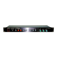
Input/output connectors, power, dimensions, and weight.

Options and Accessories

Lists optional expansion boards and standard accessories.

Safety Instructions

Servicing Precautions

Safety measures to follow during unit servicing.

Post-Servicing Safety Checks

Procedures for leakage-current and resistance checks after servicing.

Destination Symbol Key

Explanation of symbols for primary unit destinations.

Disassembly Procedures

Upper Cover Removal

Step-by-step guide for removing the upper cover.

Front Panel Removal

Instructions for detaching the front panel and knobs.

Principal Parts Location

Component Identification Diagram

Illustrated layout showing the location of major internal components.

Electrical Adjustment Procedures

Instrument Connection Setup

Diagram for connecting test equipment for adjustments.

Adjustment Point Locations

Visual guides for adjustment potentiometer locations on PCBs.

Hardware Test Mode

Entering and Exiting Test Mode

Steps to enter and exit the unit's hardware test mode.

CPU Memory Test Procedure

Instructions and expected results for the CPU memory test.

Hardware Test Procedures

Waveform Memory Test

Steps and expected outcomes for testing the waveform memory.

ADC Offset Null Confirmation

Procedure to confirm the ADC offset null status.

DAC Offset Adjustment Precautions

Important safety and preparation steps before DAC offset adjustment.

DAC Adjustments

DAC Offset Adjustment Steps

Detailed procedure for adjusting DAC offset for various channels.

DAC MSB Adjustment Steps

Procedure for adjusting DAC MSB to achieve correct waveform.

Parts List Overview

How to Use the Parts List

Guide on interpreting and using the provided parts list.

Component Categories and Keys

Explanation of part categorization and symbols used.

Recommended Spare Parts

Component Part Numbers

List of recommended spare parts with part numbers and descriptions.

PC Board Block Identification

List of main PC board blocks and their reference numbers.

PC Board Component Lists

CPU PC Board Parts

Detailed list of components on the CPU PC Board.

AD PC Board Parts

Detailed list of components on the AD PC Board.

Additional PC Board Components

Voice (1, 2) PC Board Parts

List of components for Voice (1) and Voice (2) PC Boards.

DSP PC Board Parts

Detailed list of components for the DSP PC Board.

Panel PC Board Parts

List of components found on the Panel PC Board.

Specialized PC Board Components

SMPTE, Filter, Display, Input, Power, and VR Boards

Component lists for SMPTE, Filter, Display VR, Input Jack, Power SW, and VR PC Boards.

Final Assembly Diagram

Exploded View of Components

An exploded view illustrating the assembly of the unit's parts.

PC Board Component Details

Memory, Invertor, and Final Assembly Components

Component lists for Memory, Invertor, and Final Assembly parts.

Service Manual Abbreviations

Glossary of Technical Terms

Definitions of abbreviations used throughout the service manual.

Related product manuals