3-4-1.
DAC OFF-SET ADJUSTMENT
1)
After
turning
the
unit
on, press
the
EDIT
SAMPLE button. Next use the DATA knob to select “SINE,” then press the
[REC
2]
F3/C button. Connect the
audio signal generator to the LEFT input and sample a
IKHz
sine wave. Adjust the
signal level
so that the
output
is
-6dBm. Select “tim:
s”
with the CURSOR
knob, then select
“10.00”
with the DATA
knob. Next press the [ARM] F8/H
button to sample a 1 KHz tone.
2)
Press the EDIT PROGRAM
button, then press the [KGRP] F2/B
button. Select “change number of
KEYGROUPS” with
the CURSOR knob, then
select
“12”
with the
+/<
button. Next select
“note on sample COHERENCE”
with the CURSOR
knob and select “ON” with
the DATA knob.
3)
Press the [SLCT] FI
/A button, then press the [OUT] F4/D button. Next
select “loudness” with the
CURSOR knob and
press the ENT/PLAY
button. Set the DATA knob
so
that the
output from OUTPUT (L CH, R CH) is
+
11 dBm. Select
“eft out” with the CURSOR
knob, and
14%
with the DATA knob
only when adjusting the send level.
4)
Press the ENT/PLAY
button and
adjust the VR101 (LEFT), VR201 (RIGHT) and VR301 (SEND) on the AD PCB so that
DISTORTION is less
than 1%.
5)
Select “mono
out” with the CURSOR
knob. Use the
DATA
knob to select channels between CH1-CH8 and adjust
the
appropriate
VR (refer to following
list) so that the distortion of each channel is less than
1 %.
On VOICE 1 PCB:
VR101 (CH
1)
VR201 (CH
2)
VR301 (CH
3)
VR401 (CH
4)
On VOICE 2 PCB:
VR101
(CH
5)
VR201
(CH
6)
VR301
(CH
7)
VR401
(CH
8)
3-4-2.
DAC MSB
ADJUSTMENT
1)
Press the “MARK/#”
and “NAME” buttons at the same
time
then press
the
“
~/\>
”
button to set
the default values.
Press the EDIT SAMPLE
button. Next use the DATA knob to select “SINE”,
then press the [REC
2]
F3/C
button. Con-
nect the
audio
signal
generator to the LEFT input and sample
a 100Hz sine wave. Adjust the
signal level
so
that the
output is -20dBm.
Select “tim:
s”
with the CURSOR knob, then select
“10.00”
with the DATA knob.
Next press the
[ARM] F8/H button
to sample a 100Hz tone.
2)
Press the EDIT PROGRAM
button, then press the [OUT] F4/D button.
Select “loudness” with the CURSOR
knob and
press the ENT/PLAY
button. Set the output to -60dBm with the DATA knob.
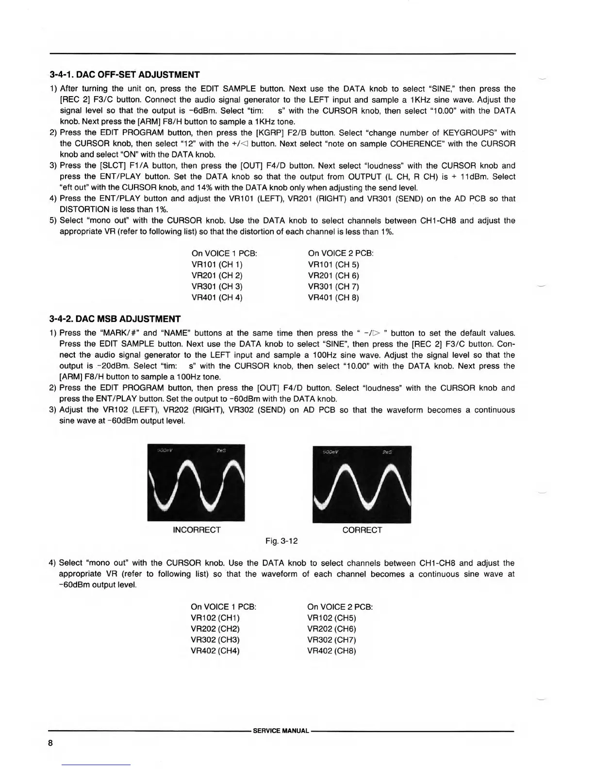
3)
Adjust the VR102 (LEFT),
VR202 (RIGHT), VR302 (SEND) on AD PCB
so that the waveform becomes a
continuous
sine wave at -60dBm
output level.
INCORRECT
i
iCOmV Ptr.
AA
CORRECT
Fig.
3-12
4)
Select “mono out” with the
CURSOR knob. Use the DATA knob to select
channels between CH1-CH8
and adjust the
appropriate VR (refer to
following list)
so
that the waveform of each channel
becomes a continuous
sine wave at
-60dBm output level.
On VOICE 1 PCB:
VR102 (CHI)
VR202 (CH2)
VR302 (CH3)
VR402 (CH4)
On VOICE
2 PCB:
VR102
(CH5)
VR202
(CH6)
VR302
(CH7)
VR402
(CH8)
SERVICE MANUAL
 Loading...