STOPPER
@PART
TRAY
BLOCK
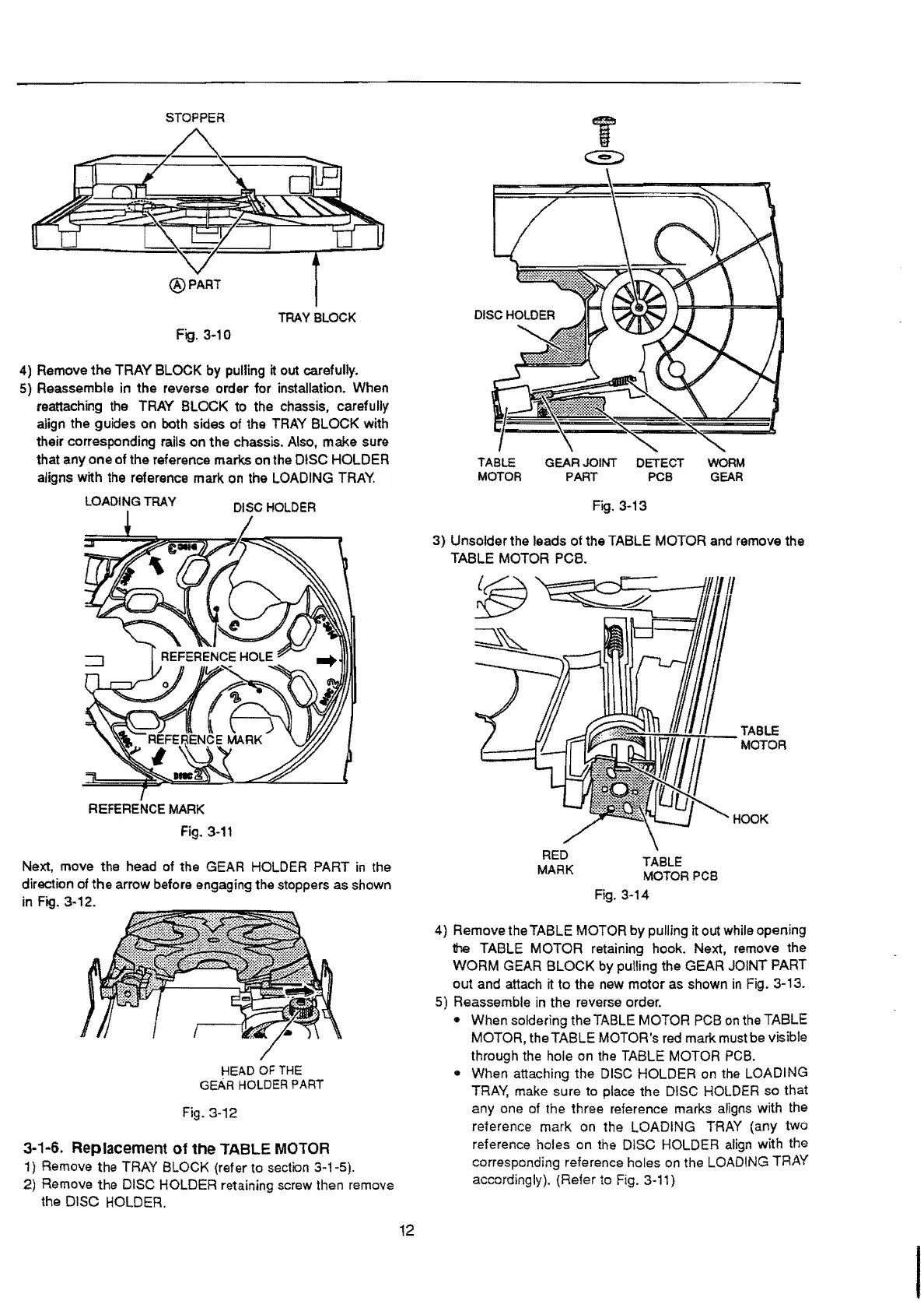
4) Remove the
TRAY
BLOCK
by
pulling
it
out carefully.
5) Reassemble in
the
reverse
order
for
installation. When
reattaching the TRAY
BLOCK
to the chassis, carefully
align the guides on both sides of the TRAY
BLOCK
with
their corresponding rails
on
the
chassis. Also,
make
sure
that any
one
of
the reference marks
on
the DISC HOLDER
aligns with the reference
mark
on the LOADING
TRAY.
LOADING
TRAY
DISC
HOLDER
REFERENCE MARK
Fig.
3-11
Next, move the head of the GEAR HOLDER PART
in
the
direction of
the arrow before engaging the stoppers
as
shown
in Fig. 3-12.
HEAD
OF
THE
GEAR
HOLDER
PART
Fig. 3-12
3-1-6. Replacement of the TABLE MOTOR
1) Remove the TRAY BLOCK (refer
to
section 3-1-5).
2) Remove
the
DISC HOLDER retaining screw then remove
the DISC HOLDER.
12
T
.
~
TABLE
GEAR
JOINT
DETECT
WORM
MOTOR
PART
PCB
GEAR
3)
Unsolder the leads
of
the TABLE MOTOR and
remove
the
TABLE MOTOR PCB.
RED
MARK
TABLE
MOTOR PCB
Fig. 3-14
HOOK
4) Remove the TABLE MOTOR by pulling it out while opening
the TABLE
MOTOR
retaining hook. Next, remove the
WORM
GEAR
BLOCK
by pulling the GEAR
JOINT
PART
out
and attach it
to
the
new
motor
as shown
in
Fig. 3-13.
5) Reassemble in
the
reverse order.
• When soldering
the
TABLE MOTOR PCB on the TABLE
MOTOR, the
TABLE
MOTOR's red mark must
be
visible
through the hole on the TABLE MOTOR
PCB.
• When attaching the DISC HOLDER on the LOADING
TRAY,
make sure to place
the
DISC HOLDER
so
that
any
one of the three reference marks aligns with the
reference
mark
on the
LOADING
TRAY (any
two
reference holes on the DISC HOLDER align with the
corresponding reference holes on the LOADING TRAY
accordingly).
(Refer
to
Fig. 3-11)
 Loading...