Do you have a question about the Akai AT-2650 and is the answer not in the manual?
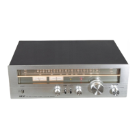
Technical specifications for the AT-2650 model.
Technical specifications for the AM-2650 model.
Step-by-step instructions for dismantling the AT-2650 model.
Step-by-step instructions for dismantling the AM-2650 model.
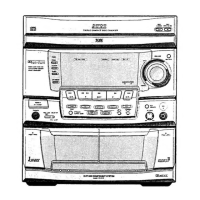
Identification and description of controls for the AT-2650 model.
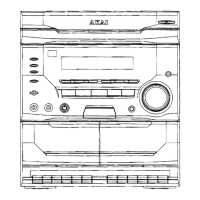
Identification and description of controls for the AM-2650 model.
Visual guide to the main components and their placement in the AT-2650.
Visual guide to the main components and their placement in the AM-2650.
Explanation of how the Phase Lock Loop circuit functions.
Explanation of the stereo demodulation process.
Details the circuit used for eliminating pulse noise.
Explains how the circuit handles stereo signals.
Procedure for adjusting the pilot signal generation circuit.
Step-by-step guide for adjusting the FM tuner section.
Step-by-step guide for adjusting the AM tuner section.
Procedure for adjusting the idling current of the amplifier.
Steps to calibrate the level meter indication.
Lists PC board titles and their corresponding identification numbers.
Details the composition of PC boards for the AT-2650 model.
Details the composition of PC boards for the AM-2650 model.
A list of suggested spare parts for the models.
List of parts for the AT-2650 Tuner PC Board.
List of parts for the AT-2650 Filter PC Board.
List of parts for the AT-2650 Power Supply PC Board.
List of parts for the AT-2650 Assembly Block.
List of parts for the AT-2650 Final Assembly Block.
List of parts for the AM-2650 Input & Tape PC Board.
List of parts for the AM-2650 Main Vol. & Balance PC Board.
List of parts for the AM-2650 Tone Control PC Board.
List of parts for the AM-2650 Main Amplifier PC Board.
List of parts for the AM-2650 Assembly Block.
List of parts for the AM-2650 Final Assembly Block.
| Brand | Akai |
|---|---|
| Model | AT-2650 |
| Category | Stereo System |
| Language | English |