Do you have a question about the Akai AC-410 and is the answer not in the manual?
Safety guidelines and precautions for handling electronic components during service.
Safety measures to prevent damage and hazards during repair procedures.
Alphabetical symbols indicating the principal destination regions for the units.
Description of test modes for adjustment, operation check, or maintenance.
Technical specifications for the tuner section, including frequency range and sensitivity.
Technical specifications for the amplifier section, including power output and frequency response.
Technical specifications for the tape deck section, including track system and frequency response.
Technical specifications for the CD player section, including pick-up system and error correction.
General technical specifications for the unit, including power requirements and weight.
Technical specifications for the speaker system, including construction and impedance.
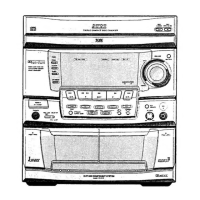
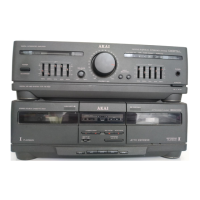
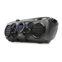
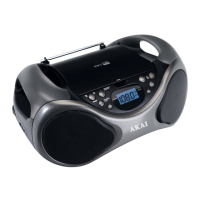
Identification and function of controls on the main unit of the component system.
Identification and function of buttons on the remote control unit.
Procedure for removing the main cover of the unit.
Procedure for removing the CD mechanism and front panel assembly.
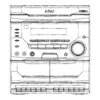
Diagram showing the location of major internal components.
Steps for disassembling the CD player block and its sub-components.
Procedure for removing the traverse mechanism from the CD player.
Steps for replacing the sled motor in the CD player mechanism.
Procedure for replacing the pick-up block in the CD player mechanism.
Steps for replacing the loading motor in the CD player mechanism.
Procedure for removing the tray block from the CD player mechanism.
Steps for replacing the table motor in the CD player mechanism.
Procedure for removing the tape mechanism blocks.
Steps for replacing the capstan motor, noting speed adjustment requirement.
Procedure for replacing the FR belt.
Procedure for replacing the main belt.
Steps for replacing the pinch roller block.
Procedure for replacing the playback or record/playback head.
Procedure for adjusting the head azimuth alignment using a test tape.
Electrical adjustments for the tape deck section in test mode.
Electrical adjustments for the CD player section in test mode.
General information and attention points for ordering parts.
List of parts for the remote control and system control printed circuit boards.
List of parts for the main printed circuit board.
List of parts for the TC-DK printed circuit board.
List of parts related to various printed circuit board blocks.
List of parts specific to the CD mechanism assembly.
List of parts for the AC-410, AC-413R, and AC-415K models.
List of parts for the AC-610, AC-613R, and AC-615K models.
List of parts for the SR-410 speaker system.
List of abbreviations used in the tuner section.
List of abbreviations used in the compact disc section.
List of abbreviations used in the cassette section.
List of abbreviations used in the amplifier section.
Overview of the system's functional blocks and their interconnections.
Detailed circuit schematics and printed circuit board layouts.
Information regarding integrated circuits used in the system.
Detailed schematic diagram for the MAIN410 printed circuit board.
Schematic diagram of the unit's power supply circuits.
Detailed schematic diagram for the CD player circuitry.
Block diagram illustrating the CD player's internal signal flow.
Schematic diagram of the main control system.
Schematic diagram of the power amplifier circuitry.
Schematic diagram for the system control (SYSCON) unit.
Schematic diagrams for the tape deck and tuner sections.
Overview of the system's functional blocks and interconnections.
Diagram showing how different parts and PCBs are connected.
Detailed schematic diagram for the MAIN410 printed circuit board.
Schematic diagram for the MAIN410(B) PCB for specific models.
Schematic diagram for the main board of 600 series models.
Schematic diagram for the SYSCON (400 series) board.
Schematic diagram for the SYSCON (600 series) board.
Pin assignment and function description for the CXA1782BQ IC.
Pin assignment and function description for the M62422FP IC.
Pin assignment and function description for the M65843AFP IC.
Pin assignment and function description for the TC9260P IC.
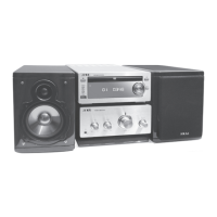
| Brand | Akai |
|---|---|
| Model | AC-410 |
| Category | Stereo System |
| Language | English |