EasyManua.ls Logo

Akai AX-M430 Service Manual

Akai AX-M430
31 pages
To Next Page IconTo Next Page
Page #1 background imageLoading...
Page #1 background image
i
AKAT
Servite
manual
DIGITAL
HIFI
MIDI
SYSTEM
move.
AX-M430
SPECIFICATIONS
[AMPLIFIER
section]
[CASSETTE
DECK
section]
Power
output
.............000..
45
W
+
45
W
(6
ohms,
EIAJ)
Frequency
responce
35
W
+
35
W
(6
ohms,
DIN)
Normal
tape...
30
Hz
to
14
KHz
|
Music
power
................05
170
W
CrO2
tape
oo...
cece
30
Hz
to
15
KHz
PMPO..
cececcccctecscvvesinsetiones
400
W
Wow
&
flutter
TD
ei
atisonvetieescisee
west
0.15
%
(1kHz)
TAPE
iss
sedetusccastacacce
ache
0.09%
(WRMS)
0.18%
(DIN)
Frequency
response.........
10
Hz
to
100
KHz
PAP
EM
ice.
destrcevieteedis
0.06%
(WRMS)
0.14%
(DN)
(10
Hz:
-1.5
dB/100
KHz:-8
dB)
|
Heads
GEQ
Center
frequency
....
63
Hz,
250
Hz,1
kKHz,4kHz,
TAPE
|
oo.
ceeceeeeseeees
HD
head
for
Playback
head
x1
16
kHz
TAPE
csstsessconttrassevccee.
HD
head
forPB/REC
hee
x1
Adjust
range
...............
+8dB
Erase
head
x1
S/N
ratio
(IHF-A)............
72
dB
(PHONO
MM)
[GENERAL]
85
dB
(etc)
Power
requirements
..........
AC220
V
-
230
V,
50
Hz
fer
Required
speaker
............
6
ohms
to
16
ohms
:
Europe
except
UK
:
impedance
(surround:8
ohms
to
16
ohms)
AC240
V,
50
Hz
for
UK
&Aus-
Input
level
/
Impedance
traria
CD
(optical)...
-22
dBm
AC110V/120V/
220
V/
20
V,
PHONO
.......
oe
1.8
mV
/
47
kohms
50
/
60
Hz
convertible
for
cher
AUX
/
VCR
we.
90
mV
/
47
kohms
countries
D/
A
Converter...
16
bit
twin
D/
A
converter
Dimensions
...........:0000
360
(W)
x
236
(H)
x
315
(Diam
Digital
filter
oo...
16
bit
/
4fs
Weight
.........000ccceeeeeeee
7.7
kg
Standard
accessories
Remote
control
unit
......
x1
Batteries
oo...
x2
Operator’s
manual........
x1
*For
improvemnt
purposes,
specifications
and
design
are
subject
to
change
without
notice.
*Noise
reduction
manufactured
under
license
from
Dolby
Laboratories
Licensing
Corporation.
“DOLBY”
and
OO
symbol
are
trademaks
of
Dolby
Licensing
Corporation.
Question and Answer IconNeed help?

Do you have a question about the Akai AX-M430 and is the answer not in the manual?

Akai AX-M430 Specifications

General IconGeneral
BrandAkai
ModelAX-M430
CategoryStereo System
LanguageEnglish

Summary

Specifications

[AMPLIFIER section]

Detailed specifications for the amplifier section, including power output and frequency response.

[CASSETTE DECK section]

Specifications related to the cassette deck, covering frequency response and wow & flutter.

[GENERAL]

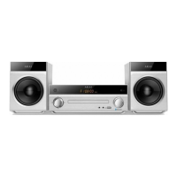
General specifications covering power requirements, dimensions, and weight of the unit.

Safety Instructions

PRECAUTIONS DURING SERVICING

Essential safety precautions to be followed during the servicing of the unit.

SAFETY CHECK AFTER SERVICING

Procedures for safety checks after servicing, including leakage and resistance tests.

MAKE YOUR CONTRIBUTION TO PROTECT THE ENVIRONMENT

Guidelines for environmentally responsible disposal of batteries.

Information

SYMBOLS FOR PRIMARY DESTINATION

Explanation of symbols indicating the primary destination countries for the unit.

PRECAUTION BEFORE/AFTER REPAIRING THE UNIT

Precautions related to power supply control and repair procedures for the unit.

VOLTAGE CONVERSION (U Model only)

Instructions for voltage selection on U model units before connecting power.

I. DISASSEMBLY

1. Removal of UPPER COVER

Step-by-step instructions for removing the upper cover of the unit.

2. Removal of the FRONT PANEL BLOCK

Procedure for safely disconnecting and removing the front panel assembly.

3. HOOKS

Illustrates the location and function of hooks used in the disassembly process.

4. Removal of the CASSETTE MECHA BLOCK

Detailed steps for detaching and removing the cassette mechanism block.

II. PRINCIPAL PARTS LOCATION

Fig. 2-1 Top view

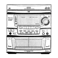
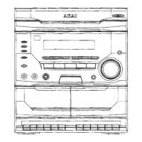
Diagram showing the top view of the unit with principal parts identified.

III. MECHANICAL ADJUSTMENT

[PRECAUTION]

Important precautions before commencing mechanical adjustments, including cleaning heads.

3-1. CONFIRMATION OF THE WINDING TORQUE IN EACH MODE

Procedure to confirm winding torque for play back and fast forward/rewind modes.

3-2. ADJUSTMENT OF THE TAPE GUIDE HEIGHT (TAPE II)

3-3. ADJUSTMENT OF THE PB HEAD AZIMUTH ALIGNMENT (TAPE I)

3-4. ADJUSTMENT OF THE REC/PB HEAD AZIMUTH ALIGNMENT (TAPE II)

IV. ELECTRICAL ADJUSTMENT

[PRECAUTIONS BEFORE ADJUSTMENT]

Precautions before starting electrical adjustments, including head cleaning.

ABOUT THE TEST MODE

Instructions on how to engage and disengage the test mode for adjustments.

1. TEST TAPE/INPUT SIGNAL

Details on the test tape and input signals required for electrical adjustments.

2. MODE

Specifies the modes to be used during electrical adjustment procedures.

3. TEST POINT/ADJUSTMENT PART

Identifies the specific test points and adjustment parts for electrical calibration.

4. (+) REMAKERS, (*) RESULT

Indicates special notes, remarks, and expected results for adjustments.

V. PARTS LIST

ATTENTION

Important notices regarding ordering parts and potential changes in part numbers.

HOW TO USE THIS PARTS LIST

Guide on how to interpret and use the provided parts list effectively.

WARNING

Critical safety warning about replacing safety-critical components.

1. RECOMMENDED SPARE PARTS

2. MECHA BLOCK

3. MECHA BLOCK (REVERSE)

4. P.C BOARD

MAIN P.C BOARD

List of components and their references for the Main Printed Circuit Board.

OPERATION P.C BOARD

List of components and their references for the Operation Printed Circuit Board.

7. PRE AMP P.C BOARD

8. GEQ P.C BOARD

9. MAIN VR P.C BOARD

10. POWER SW P.C BOARD

FINAL ASSEMBLY

11. FINAL ASSEMBLY

ABBREVIATIONS (AMPLIFIER)

List of abbreviations used in the amplifier section of the manual.

12. ACCESSARY

ABBREVIATIONS (CASSETTE)

SCHEMATIC DIAGRAMS AND PC BOARDS

I. BLOCK DIAGRAMS

Overview of the unit's system through block diagrams.

II. SCHEMATIC DIAGRAMS AND PC BOARDS

Detailed schematic diagrams and Printed Circuit Board layouts.

III. INFORMATION OF ICs

Information and details regarding integrated circuits used in the system.

AX-M430 SIGNAL BLOCK DIAGRAM

AX-M430 SYSTEM CONTROL BLOCK DIAGRAM

AX-M430 CONNECTION DIAGRAM

AX-M430 MAIN SCHEMATIC DIAGRAM

PRINCIPAL PARTS LOCATION

ICS

List of Integrated Circuits (ICs) with their principal locations.

CONNECTORS

List of connectors with their principal locations on the PCB.

TRANSISTORS

List of transistors with their principal locations on the PCB.

MAIN VR PCB C1028A503B

GEQ PCB C1028A503A

AX-M430 GEQ SCHEMATIC DIAGRAM

POWER SW PCB C1028A503C

Related product manuals