Do you have a question about the Åkerströms SESAM 800 and is the answer not in the manual?
Main features: 6 solid state outputs, pre-programmed logic, waterproof (IP67).
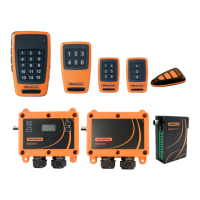
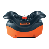
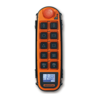
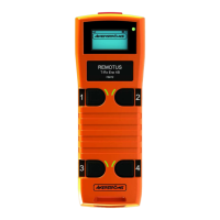
Describes M6 (6-button) and L99 (display) transmitters, their ruggedness and waterproof rating.
Explains the meaning of LED indicators on the Sesam 800 RXM receiver (Power, Squelch, Status, Learn, Output LEDs).
Details steps for selecting location, drilling holes, mounting the receiver, and connecting wiring for outputs and power supply.
Details the function of buttons on the M6 and L99 Sesam transmitters, including a comparison table.
Explains normal operation and battery warning indicators for transmitter LEDs.
Explains unique and Group IDs for L99 transmitters, their function, and maintenance benefits.
Step-by-step guide to configure a six-digit Group ID on the L99 transmitter.
Instructions on how to turn the L99 transmitter's display illumination ON or OFF.
Procedure for replacing batteries in the M6 transmitter, including screw torque and handling precautions.
Procedure for replacing batteries in the L99 transmitter, including screw torque and handling precautions.
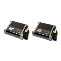
Describes the logic and installation of the optional 4-channel digital input module.
Details jumper settings and connection of the digital input card.
Details the serial output module, its function, and communication settings.
Instructions for installing the RS232 serial output module, including cable requirements and jumper settings.
| Frequency | 433.92 MHz |
|---|---|
| Operating Temperature | -20°C to +55°C |
| Protection Class | IP65 |
| Battery Life | Up to 2 years |
| Dimensions | 120 x 60 x 30 mm |
| Channels | 8 |
| Range | Up to 100 m |