IN6 INPUT BOARD:
The IN6 input board does not require power supply. The 12 vdc power comes from
the RS485 port. If you are using a single IN6 board, use the RJ12 cable to connect
the IN side of the RS485 port of the IN6 board into the SR6’s RS485 port.
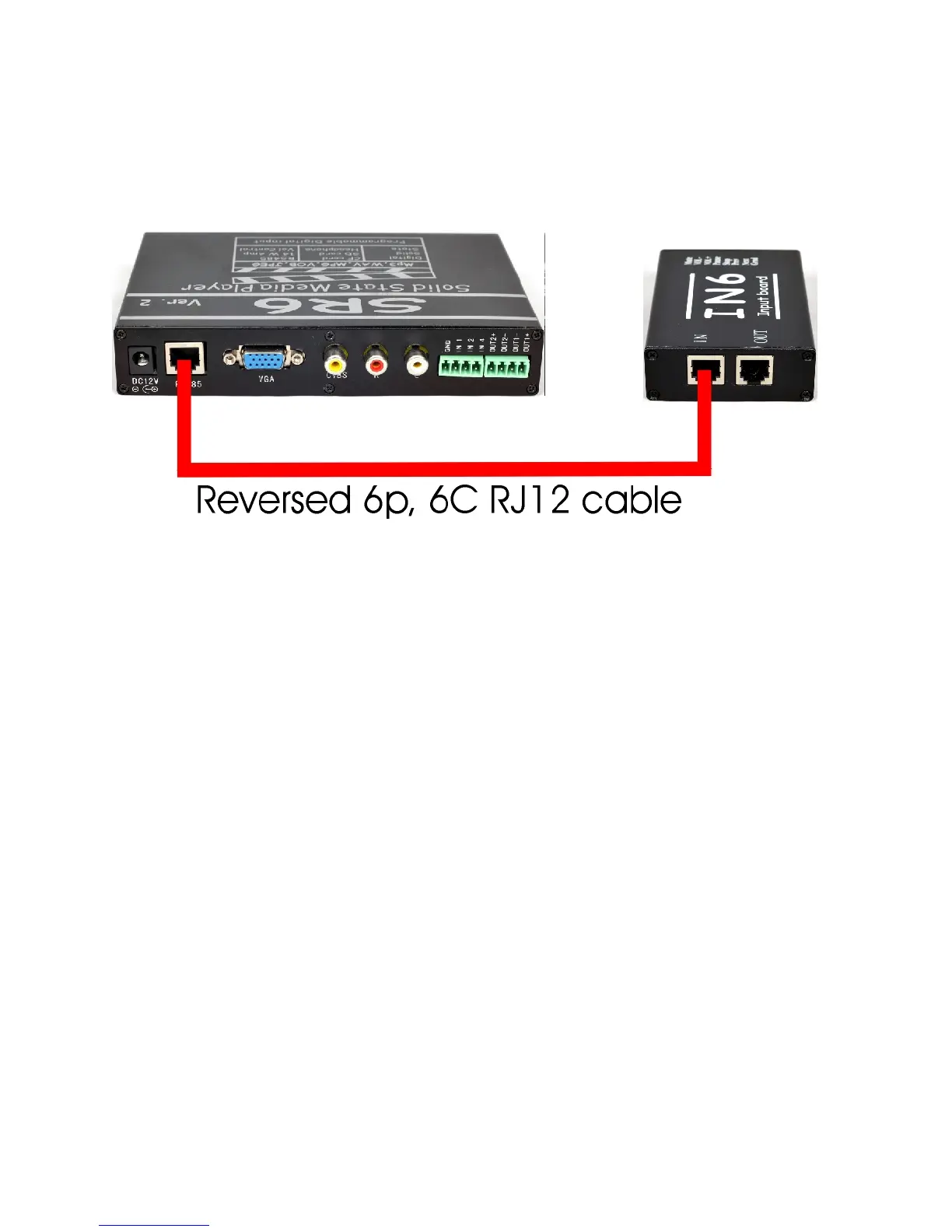
How to connect SR6 into IN6:
Use RJ12 cable that comes with the IN6 unit. This RJ12 cable is a 6 pin, 6
conductor reversed cable.
Note: when an input is triggered, the green LED will blink rapidly.
Using the RJ12 cable, connect one end into the SR6 and the other end into the IN
port of the IN6. To connect the second IN6 board, use the RJ12 to connect the
OUT port of the first IN6 board into the IN port of the second IN6 board. Make
sure to set the IN6 board address correctly. To connect the third IN6 board, use the
RJ12 to connect the OUT port of the second IN6 board into the IN port of the third
IN6 board. Make sure to set the IN6 board address correctly. Do the same for the
fourth IN6 board.
IN6 BOARD ADDRESS:
Each board can be set for a board address 1,2,3 OR 4. The address is set using
switch1 and 2 of the Dip Switch located at the rear of the IN6.
If SW1 and SW2 are OFF (Down position), the board address is 0.
The digital input of IN6 is 1 to 12.
If only SW1 is ON (Down position) board address is 1.
The digital input of IN6 is 13 to 24.
If only SW2 is ON (Down position) board address is 2.
The digital input of IN6 is 25 to 36.
If SW1 and SW2 are ON (all down) board address is 3.
The digital input of IN6 is 37 to 48.