AL Level 2 ALARM control (Visual)
Level 3 Description Values Min. Def. Max.
A0
Configuration of temperature alarms
001
(0 = Relative to SP) (1 = Absolute)
A1 Maximum alarm in sensor 1 (ºC/ºF) A2 99.9 99.9
A2 Minimum alarm in sensor 1 (ºC/ºF) -50.0 -50.0 A1
A3
Temperature alarm delay in the start-up
(min.)
00120
(If programmed in A1, A2)
A4 Temperature alarm delay from the end of a defrost (min.) 0099
A5
Temperature alarm delay from the (min.)
0 30 99
moment at which they should operate due to temperature
A8
Signals if defrost ends due to maximum time:
001
(0=Led DT OFF) (1=Led DT ON)
A10 Differential Alarms Temperature A1 and A2 (ºC/ºF) 0.1 1.0 20.0
EP Exit to Level 1
CnF Level 2 GENERAL STATUS
Level 3 Description Values Min. Def. Max.
P1 Delay of all functions on power supply switch on (min.) 0099
P2
Allocation of password to Set Point:
001
(0=Without allocation) (1=With allocation of L5 password)
P3
Initial parameters: (1=YES, configure to “Def” and exit programming)
001
P4 Connected sensors: (1=Sensor 1) (2=Sensor 1 + Sensor 2) 112
P5 Address for units with communication 00126
P6
Relay 2 (F2) function in 2 relay versions:
001
(0=Defrost) (1=Fans control)
Temperature display mode:
P7 (0=Integers in ºC) (1=One decimal in ºC) 013
(2=Integers in ºF) (3=One decimal in ºF)
P8 Sensor to be displayed: (1=Sensor 1) (2=Sensor 2) 112
EP Exit to Level 1
tid Level 2 ACCESS AND INFORMATION control
Level 3 Description Values Min. Def. Max.
L5 Access password to parameters and information 0099
L6
Parameters transfer: (0=Disabled) (1=Send) (2=Receive)
002
PU Program version (Information)
EP Exit to Level 1
EP Exit programming
Nos reservamos el derecho de suministrar materiales que pudieran diferir levemente de los
descritos en nuestras Hojas Técnicas. Información actualizada en nuestra web: www.ako.com.
Av. Roquetes, 30-38 | 08812 Sant Pere de Ribes | Barcelona | España
Tel. (34) 938 142 700 | Fax (34) 938 934 054 | e-mail: ako@ako.com | www.ako.com
Apartado (P.O. Box), 5 | 08800 Vilanova i la Geltrú | Barcelona | España
AKO ELECTROMECÀNICA, S.A.L.
351422302 REV.01 2008
D.L.: B-24.971-06
CHANGE
NUMBER
DISPLAY
VALUE
PASSWORD
REQUEST
ENTER
PASSWORD
DISPLAY
PASSWORD
CURRENT
VALUE
NEW
VALUE
I
F L5=0
ACCEPT
THE NEW
C
URRENT
T
EMPERTATURE
L
EVEL 2
P
ARAMETERS
L
EVEL 3
V
ALUES
E
XIT TO
LEVEL 1
ACCEPT
PASSWORD
P
ASSWORD
I
F PROGRAMMED
CHANGE
VALUE
L
EVEL 1
M
ENUS
10 Sec.
E
XIT
PROGRAMMING
ACCEPT
ACCEPT
S
IMULTANEUSLY
S
IMULTANEUSLY
S
IMULTANEUSLY
S
IMULTANEUSLY
SIMULTANEUSLYSIMULTANEUSLY
Level 3 Values
- To DISPLAY the CURRENT VALUE of any parameter, select the required one and press
+ keys simultaneously. Once it is displayed, you can CHANGE VALUE, pressing or
key.
- Press + keys simultaneously to ACCEPT THE NEW. The programming returns to
LEVEL 2 PARAMETERS.
REMARK: If no key is pressed for 25 seconds in either of the previous steps, the controller
will automatically return to the CURRENT TEMPERATURE display status without modifying
any of the parameters values.
6- Description of parameters and messages
Values in the Def. column are factory-set.
Level 1 Menus and Description
rE Level 2 REFRIGERATION control (Compressor)
Level 3 Description Values Min. Def. Max.
C0 Sensor 1 calibration (Offset) (ºC/ºF) -20.0 0.0 20.0
C1 Sensor 1 differential (Hysteresis) (ºC/ºF) 0.1 2.0 20.0
C2
Set Point upper limit
(ºC/ºF) C3 99.9 99.9
(It cannot be set above this value)
C3
Set Point lower limit
(ºC/ºF) -50.0 -50.0 C2
(It cannot be set below this value)
C4
Compressor protection delay type: 001
0=OFF/ON ((From the last switch-off) 1=ON (At switch-on)
C5
Protection delay time
(min.) 0099
(Value for the option selected in parameter C4)
“COOL” (Compressor) relay time in ON
C7 in case of faulty sensor 1 (min.) 0 10 99
(If C7=0 and C8≠0, the relay will always be OFF disconnected)
“COOL” (Compressor) relay time in OFF
C8 in case of faulty sensor 1 (min.) 0599
(If C8=0 and C7≠0, the relay will always be ON connected)
EP Exit to Level 1
dEF Level 2 DEFROST control
Level 3 Description Values Min. Def. Max.
d0 Defrost frequency (Elapsed time between 2 starts) (h.) 0699
d1 Defrost maximum duration (min.) 0 30 99
Type of message during defrost:
(0=Current temperature display)
d2
(1=Defrost start temperature display)
022
(2=Display dEF message)
d3
Message maximum duration (Time added at the end of defrost)
(min.)
0599
d4
Defrost final temperature by sensor 2
(ºC/ºF) -50.0 8.0 99.9
(If programmed in P4) In 2 relay versions, it operates if P6=0
d5
Defrost start-up on equipment switch-on:
001
(0=NO, first defrost according to d0) (1=YES, first defrost according to d6)
d6 Defrost start-up delay on equipment switch-on
(min.)
0099
d7
Defrost type: (0=Electric heat) (1=Hot gas by-pass)
001
To defrost by air in 2 relays, parameters P6 and F3 should be programmed
d8
Time calculation between defrost periods:
001
(0=Total real time) (1=Compressor operation sum)
d9
Drip time, compressor stop and FAN/R2
(min.) 0199
relay off when defrost ends
EP Exit to Level 1
FAn Level 2 FANS control (Evaporator)
Level 3 Description Values Min. Def. Max.
F0
Fans stop temperature by sensor 2
(ºC/ºF) -50.0 4.0 99.9
(If programmed in P4)
F1 Sensor 2 differential (ºC/ºF) 0.1 2.0 20.0
F2
Stop fans, when compressor stops?:
001
In 2 relays versions, R2 operates if P6=1
F3
Fans status during defrost:
001
(0=Off) (1=On)
F4
Start-up delay after defrost
(min.) 0399
(Operates if it is higher than d9)
EP Exit to Level 1
REMARK: When time parameters are modified, the new values are applied when the current
cycle is completed. In order for it to have an immediate effect, switch the controller off and
then on again.
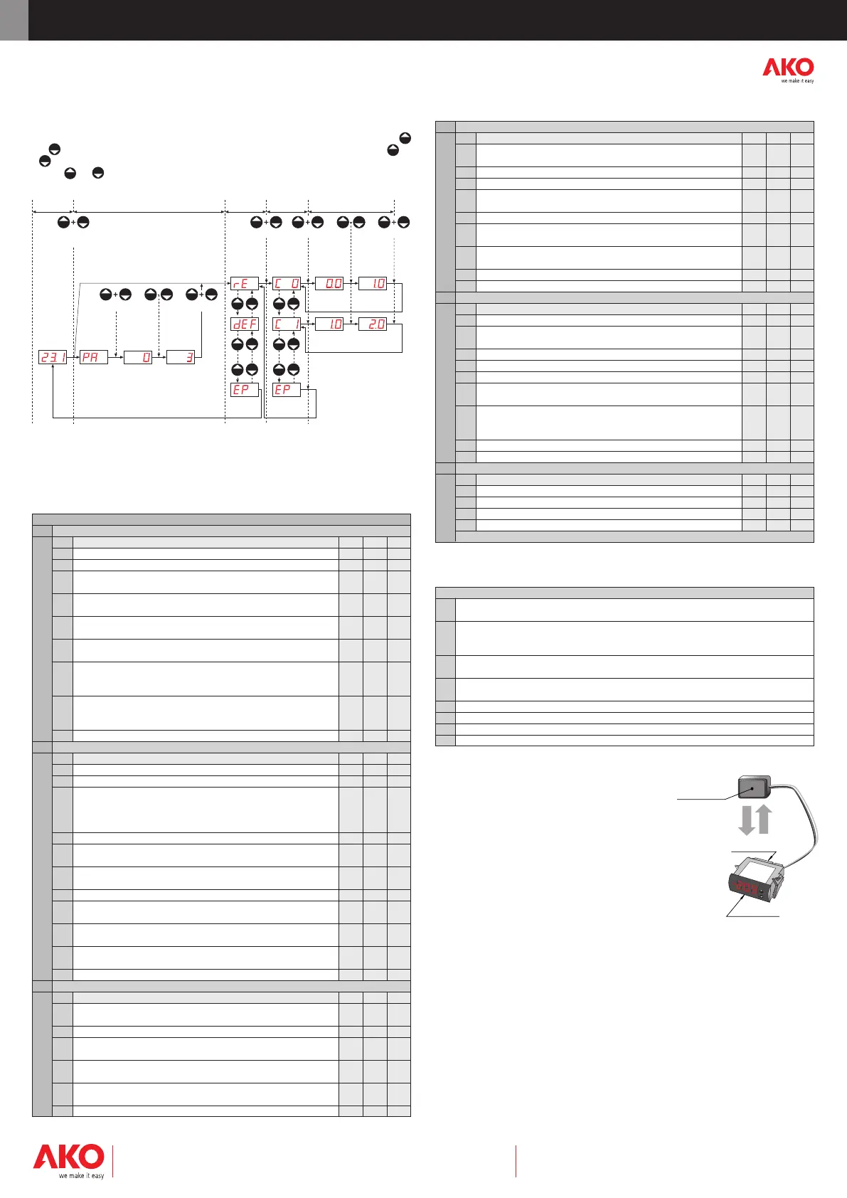
7- Parameters transfer
Portable server
AKO-14918 portable server, with no power supply, in
which parameters programmed in a powered controller
can be copied by transfer. Parameters can be transferred
again from the server to other identical powered con-
trollers.
To transfer parameters, other servers are available for
controllers that should be programmed identically in
high quantity without power supply.
9- Warnings
The use of the unit without observing the manufacturer's instructions may alter its safety
qualification.
To ensure correct operation of the apparatus, only NTC type probes supplied by AKO should
be used.
Between -40 ºC and +20 ºC, when the probe is extended up to 1.000 m with minimum
0,5 mm
2
cable, deviation will be less than 0.25 ºC (Probe extension cable ref. AKO-15586).
(*) The intensity specified for each relay is its maximum individual value; if more
than one is connected, the intensity of the addition (COMPRESSOR + DEFROST
+ FAN) must not exceed the total maximum intensity specified in the rating
plate.
8- Maintenance
Clean the controller surface with a soft cloth, soap and water. Do not use abrasive deter-
gents, petrol, alcohol or solvents.
Transfer
Power supply
Programming
AKO-14918
MESSAGES
PA
Password request to enter programming parameters
or SET POINT
It indicates defrosting is being carried out. In order to display "dEF"
dEF during defrosting, it is essential that parameter d2
is set to option 2.
AH
Flashing with temperature - Sensor 1 temperature exceeds the parameter
programmed in A1
AL
Flashing with temperature - The Sensor 1 temperature is lower than the
parameter programmed in A2
E1 Sensor 1 failure (Open circuit, crossed, temp.> 110ºC or temp.<-55ºC)
E2 Sensor 2 failure (Open circuit, crossed, temp.> 110ºC or temp.<-55ºC)
ES Incorrect sensor configuration (See P4, P8)
EE Memory failure
 Loading...