Installation instructions
GB
D163H232 Ed.06
AKO-D16323
35D163232 REV.05 2016
AKO ELECTROMECÀNICA, S.A.L.
We reserve the right to supply materials which may be slightly
different from those described in our Data Sheets. Updated
information on our web site: www.ako.com
Av. Roquetes, 30-38
08812 Sant Pere de Ribes
Barcelona (España)
www.ako.com
ako@ako.com
Tel. (34) 938 142 700
Fax (34) 938 934 054
1- Warnings
-Using the equipment without following the manufacturer's instructions
may affect the device's safety requirements. To ensure that the device
operates correctly, only probes supplied by AKO should be used.
-The unit must be installed in a location protected from vibrations, water
and corrosive gases, where the ambient temperature does not exceed
that shown in the technical data.
-To ensure a correct reading, the probe must be situated in a location
without any external heat influences except for the temperature which
is being measured or controlled.
-The power supply circuit must be provided with a main switch rated at at
least 2 A, 230 V, located close to the equipment. The cables will enter
through the back and should be type H05VV-F or H05V-K.
-The gauge will depend on local regulations, but should in no case be less
2
than 1 mm .
2
-Connecting wires for the relay contacts should be sized 2.5 mm .
-Between -40 ºC and +20 ºC, if the probe NTC is prolonged till 1.000 m with a
2
mínimum of cable 0,5 mm , the maximum deviation will be of 0,25 ºC
(extension cable for probe ref. AKO-15586)
NOTE: Equipment not compatible with AKO-14917 (external communication
module) and AKO-14918 (programming key)
2- Installation
3- Wiring
The probe and its cable should NEVER be installed in the same conduit
as power, control or supply cables.
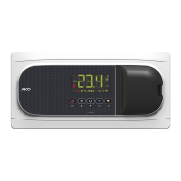
4- Operation
COOL relay ON
FAN relay ON
DEF relay ON
Alarm ON
Temperature
indication
Terminal blocks
UP (N) /SET key
DOWN (Q) key
UP(N) /SET key
Pressing for 5 seconds activates Standby mode, pressing for 2
seconds returns the equipment to normal mode. In Standby mode,
the equipment performs no actions and only the AKO indicator is
displayed on the screen.
Pressing for 10 seconds goes to the programming menu.
In the programming menu, pressing for 5 seconds goes to the level
displayed or, during the setting of a parameter, accepts the new value.
In programming menu, pressing briefly allows you to scroll through the
various levels or, during the setting of a parameter, to change the value.
DOWN (Q) key
In programming menu, pressing briefly allows you to scroll through the
various levels or, during the setting of a parameter, to change the value.
5- Start-up
On power-up, the equipment will start in Wizard mode (InI / 1
flashing), select the most appropriate application using the UP /
DOWN keys and press SET.
1: Multipurpose 2: Frozen 3: Fruits and vegetables
4: Fresh fish 5: Soft Drinks 6: Bottle racks
7: AC
The wizard will configure the parameters of the equipment for the
chosen application (see table "Default settings by application").
124 mm
85 mm
16 A
16 A
6 A
S1
S2
DI1
DI2
1 82 93 104 115 126 137
AKO-D16323
COOL
CRANKCASE HEATER
FAN
I m
ax.:
16 A
L N
90-240 V~
50/60 Hz
5 sec.
Temperature
Indication
Release
SET to go to
Stand-by
Release SET
to access
programming
10 sec.
t
Change
Menu
Change
Parameters
Level 1
Menus
Temperature
indication
Level 2
Parameters
Level 3
Values
OK
Press
UP/
SET
>10 sec.
Press
UP/
SET
<5 sec.
Press
UP/
SET
<5 sec.
Press
UP/
SET
<5 sec.
Press
UP/
SET
>5 sec.
Press
UP/
SET
<5 sec.
Press
UP/
SET
<5 sec.
Press
UP/
SET
repeatedly
Press
UP/
SET
repeatedly
Press
UP/
SET
<5 sec.
Press
UP/
SET
<5 sec.
OK
20 sec20 sec20 sec
OKOK
OUT OF
PROGRAMMING
PROGRAMMING
Change
value OK
Keep
UP / SET
pressed
Programming Menu (parameters)
Access to set point and Stand-by
After 20 seconds with no key being pressed, the equipment will return to the previous level. If you are on level 3, the changes will not be saved.