Device designed to display, control and regulate cooling generators (manual or automatic
programmable defrosting). Auxiliary relay configurable for indicating alarms, defrost 2nd
evaporator o solenoid control. Possible stop for pump down. Input for independent probe or
defrost control in 2nd evaporator.
1464H202 Ed.01
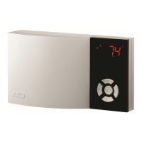
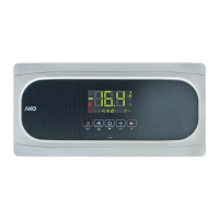
Surface temperature controller with 4 relays and 3 probes
GB
MODEL FUNCTION RELAY
POWER SUPPLY,
50/60 Hz
COOL: 16 A, 250 V, cos ϕ=1, SPST
AKO-14641 Controller DEF: 8 A, 250 V, cos ϕ=1, SPDT 120 V~
FAN: 6 A, 250 V, cos ϕ=1, SPST +8% -12%
AUX: 6 A, 250 V, cos ϕ=1, SPST
COOL: 16 A, 250 V, cos
ϕ=1, SPST
AKO-14642 Controller DEF: 8 A, 250 V, cos ϕ=1, SPDT 230 V~
FAN: 6 A, 250 V, cos ϕ=1, SPST ±10%
AUX: 6 A, 250 V, cos ϕ=1, SPST
1- Versions and references
2- Technical data
T
emperature range: . . . . . . . . . . . . . . . . . . . . . . -50.0 ºC to 99.9 ºC (-58.0 ºF to 211 ºF)
Resolution, Set Point and differential: . . . . . . . 0,1 or 1 ºC/ºF configurable by parameter P7
Input for NTC probe: . . . . . . . . . . . . . . . . . . . . . . . . . . . . . . . . . . . . . . . . . . . AKO-149XX
T
hermometric accuracy: . . . . . . . . . . . . . . . . . . . . . . . . . . . . . . . . . . . . . . . . . . . . . . ± 1 ºC
Probe tolerance at 25 ºC: . . . . . . . . . . . . . . . . . . . . . . . . . . . . . . . . . . . . . . . . . . . ± 0,4 ºC
Maximum input power:. . . . . . . . . . . . . . . . . . . . . . . . . . . . . . . . . . . . . . . . . . . . . . . . 7 VA
W
orking ambient temperature: . . . . . . . . . . . . . . . . . . . . . . . . . . . . . . . . . . . 5 ºC to 50 ºC
Storage ambient temperature: . . . . . . . . . . . . . . . . . . . . . . . . . . . . . . . . . . -30 ºC to 70 ºC
Control device classification:
Independent mounting,
with characteristic of automatic operation Type 1.B action, to be
used in a clean situation, logical medium (software) class A and continuous operation.
Degree of contamination 2 on UNE-EN 60730-1.
Double insulation between the power supply, the secondary circuit and the relay output.
Allocated pulse temperature: . . . . . . . . . . . . . . . . . . . . . . . . . . . . . . . . . . . . . . . . . 2500 V
Pressure ball test temperature:
Accesible parts: . . . . . . . . . . . . . . . . . . . . . . . . . . . . . . . . . . . . . . . . . . . . . . . . . . 75 ºC
Parts that position active elements: . . . . . . . . . . . . . . . . . . . . . . . . . . . . . . . . . . 125 ºC
Voltage and current declared by the EMC tests: . . . . . . . . . . . . . . . . . . . . . 207 V, 23 mA
Current of radio jamming supression test: . . . . . . . . . . . . . . . . . . . . . . . . . . . . . . . 270 mA
3.2 Connection:
The probe and its lead should
NEVER be installed in ducting
along with power, control or
power supply wiring.
The power supply circuit should be
connected with a minimum 2
A,
230 V, switch located close to the
unit. Power supply cables should
be H05VV
-F 2x0,5 mm
2
or H05V
-K
2x0,5 mm
2
.
Section of connecting wires for
relays contacts should be 2,5 mm
2
.
3- Installation
The controller should be installed in a place protected from vibrations, water and corrosive
gases, and where ambient temperature does not surpass the value specified in the technical
data.
In order to give a correct reading, the probe should be installed in a place without heat
influences other than the temper
ature that is to be measured or controlled.
DEF
1
2
4
5
8
3
9
10
11
12
13
14
±
10% 50/60 Hz
COOL
C
S1-TEM
S2-DEF
DI1
*16A
*8A
*6A
*Imax = 16 A
cos
ϕ
=1 250 V
230V~
In=23mA~
6
FAN
15
*6A
AUX
DI2
S3-AMB
AKO-14642
DEF
1
2
4
5
8
3
9
10
11
12
13
14
−
12% 50/60 Hz
COOL
C
S1-TEM
S2-DEF
DI1
*16A
*8A
*6A
*Imax = 16 A
cos
ϕ
=1 250 V
120V~ +8%
In=54mA~
6
FAN
15
*6A
AUX
DI2
S3-AMB
AKO-14641
4- Front panel functions
LED Cool (Compressor)
Permanent: Cooling relay COOL (com-
pressor) energised.
Flashing: Because of the temperature
detected by Sensor 1 (TEM),
the COOL
relay should be energised,
but is no due to
a programmed parameter.
LED Fan
Permanent:
F
AN relay energised.
Flashing: Because of the temperature
detected by Sensor 2 (DEF), the Fan relay
should be energised, but is no due to a pro-
grammed parameter.
LED Def
Permanent: Indicates defrost in opera-
tion.
LED Alarm
Permanent: Alarm indicator enabled.
Flashing: Alarm detected,
but display
maintained.
LED
COOL
ºC
ºF
LED
DEF
LED
ºC
LED
ºF
LED C
ontinuous
Cycle
DOWN
Key
RIGHT
Key
SET
Key
UP
Key
LEFT
Key
LED
Fan
LED
Alarm
LED DT
LED
AU
X
LED AUX
Permanent: AUX relay indicator enabled
by key. If CAU=1.
LED DT
Permanent: Indicates last defrost ended
by time.
LED Continuous cycle
Permanent: It indicates that the conti-
nuous cycle is active
LED ºC
Permanent: Degrees ºC indicator.
Flashing: Programming phase
LED ºF
Permanent: Degrees ºF indicator.
Flashing: Programming phase
UP Key
- Press once to cancel the alarms, but they
remain displayed.
- In programming, it makes the displayed
value increase.
- When pressed it displays the help messa-
ge dEF corresponding to the short key
function that it performs.
- When pressed for at least 5 seconds, a
manual defrost is started / stopped with
programmed duration.
DOWN Key
- Press once to cancel the alarms, but they
remain displayed.
- In programming, it makes the displayed
value reduce.
- When pressed, it displays the help mes-
sage Con corresponding to the function
performed by the key.
- Pressing during 3 seconds,it activates /
deactivates the CONTINUOUS CYCLE
during the time for which it has been
programmed.
RIGHT Key
- Press once to cancel the alarms, but they
remain displayed.
- In programming, it makes the level value
increase.
- When pressed, it displays the help mes-
sage oFF corresponding to the function
performed by the key.
- Pressing during 3 seconds it turns off/on
the unit leaving it in STAND-BY. The dis-
play shows oFF when the unit is discon-
nected.
LEFT Key
- Press once to cancel the alarms, but they
remain displayed.
- Exit programming level.
Key
- Press once to cancel the alarms, but they
remain displayed.
- In programming, accept the programmed
new value.
- When pressed it displays the help messa-
ge SP corresponding to the function per-
formed by the key.
- When pressed for at least 5 seconds, the
SP Set Point temperature is displayed.
Keys + +
- Press simultaneously to change the dis-
play from Probe 1 to Probe 2 and vice
versa for 5 seconds.
5.2 Parameters configuration
Level 1
Menus
When the k
eys + are pressed simultaneously for at least 10 seconds, the display
shows Pro for 10 seconds. LED ºC or ºF will be flashing, we are in the programming LEVEL
1 MENUS and the first menu “rE” is displayed.
- Press key to access the next menu and key to return to previous one.
- Pressing key, the controller returns to the CURRENT TEMPERATURE display status and
LED ºC or ºF will stop flashing.
When
P
A
is displayed,
P
ASSWORD progr
ammed in
L5 of
“
tid”
menu should be entered to
access progr
amming LEVEL 1 MENUS
.
- Press key.
0 will be displayed to ENTER PASSWORD.
- Press or keys to CHANGE NUMBER and DISPLAY PASSWORD programmed.
-
Press key to ACCEPT PASSWORD. The first menu “
rE”
will be displayed.
Detail of fixing screw-holes.
Ø max 3.7
Suitable fixing screw-holes for universal
flush-mounting wall box
.
Press down lightly
to open the cover.
CURRENT
TEMPERATURE
ACCEPT
PASSWORD
DISPAY
SET POINT
CHANGE
SET POINT
ACCEPT
THE NEW
ENTER
PASSWORD
DISPLAY
PASSWORD
CURRENT
SET POINT
NEW
SET POINT
If P2=0 or L5=0
PASSWORD
REQUEST
CHANGE
NUMBER
5 Sec.
5- Adjustment and configuration
It should only be programmed or modified by personnel who are fully conversant with the
equipment operation and possibilities.
5.1 Set Point temperature
The factory SET POINT default value is 0.0 ºC.
- Press key for at least 5 seconds to DISPLAY SET POINT. Displays
SP
for 5 seconds. It
displays the CURRENT SET POINT value and LED ºC or ºF starts flashing.
- Press or keys to CHANGE SET POINT into the required value.
- Press key to ACCEPT THE NEW SET POINT. The display returns to the CURRENT TEM-
PERATURE display status and LED ºC or ºF stops flashing.
- Press the key to exit the temperature set point without modifying the value.
When
PA is displayed, PASSWORD programmed in L5 parameter of tid menu should be
entered to access the CURRENT SET POINT.
- Press key.
0 will be displayed to ENTER PASSWORD.
- Press or keys to CHANGE NUMBER and DISPLAY PASSWORD programmed.
-
Press
k
ey to ACCEPT PASSWORD. The CURRENT SET POINT value will be displayed
and it can be already modified.
DEF
1
2
4
5
8
3
9
10
11
12
13
14
±
10% 50/60 Hz
COOL
C
S1-TEM
S2-DEF
DI1
*16A
*8A
*6A
*Imax = 16 A
cos
ϕ
=1 250 V
230V~
In=23mA~
6
FAN
15
*6A
AUX
DI2
S3-AMB
AKO-14642
DEF
1
2
4
5
8
3
9
10
11
12
13
14
−
12% 50/60 Hz
COOL
C
S1-TEM
S2-DEF
DI1
*16A
*8A
*6A
*Imax = 16 A
cos
ϕ
=1 250 V
120V~ +8%
In=54mA~
6
FAN
15
*6A
AUX
DI2
S3-AMB
AKO-14641
3.1 Fastening
PROBES
PROBES