GB
Translation of original user instructions
10
AL-KO Lifting Support
Installation
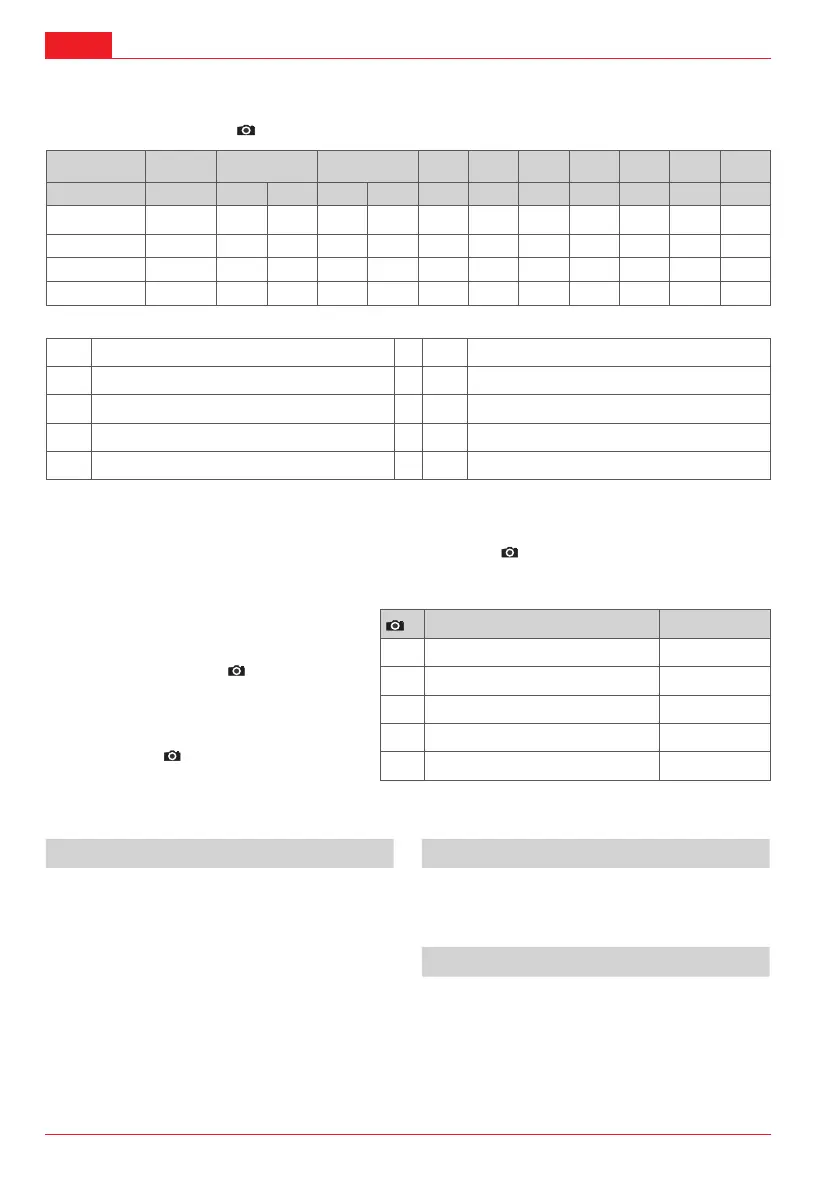
Installation dimensions - A
A B C D E F F
B
G H I M
min. max. min. max.
1239300/301 1239362 310 424 281 445 140 364 302 40 41.5 45 200
1239339/340 1239363 320 440 297 464 142 382 320 40 41.5 45 200
1239346/347 1239364 420 624 397 654 150 481 419 40 41.5 45 200
1239351/352 1239365 460 710 446 744 155 531 469 40 41.5 45 200
*
all dimensions in mm
A Order number for lifting support F Dimensions of support
B Order number for lifting support installation kit G Installation dimensions
C Required frame height H Installation dimensions
D Height of support I Installation dimensions
E Dimensions of support M Drive shaft length
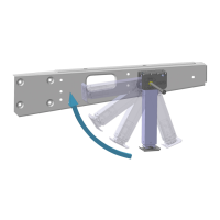
Installation variants
The lifting supports are screwed onto the frame in the specied positions ( A). Tightening torque: 45 - 50 Nm.
There are 2 different installation variants:
Installation variant A with collar knockouts
in the frame
Series installation (
2 -a)
2 Designation Quantity / side
1
Lifting support 1
2
Frame 1
Installation variant B without collar knock-
outs and holes in the frame
Retrot (
2 -b)
3
M10 hexagon nut (DIN 985-10) 2
4
Plate (604147) 1
5
Installation plate (1239370) 1
Operation
Before use Lowering the support
Apply the hand brake
On soft ground, use an appropriate base
On uneven ground, use chocks or levelling blocks
Avoid one-sided loading when lowering supports
Push on crank handle and turn in the direction indi-
cated by the arrow labelled “PARK”.
Retracting the support
Push on crank handle and turn in the direction indi-
cated by the arrow labelled “DRIVE”.