Electrical connections
The circuit for the toilet power supply must be independent and cannot be used for any other appliance.
Connect the battery positive terminal to a fuse of adequate capacity load. See wiring dimensions table.
For the Rocker Switch Control panel, connect the wires from the discharge and rinse pump as follows:
1. Panel Red to positive battery terminal (+)
2. Panel Brown to Flush Pump / Solenoid Valve positive (+)
3. Panel Yellow to Discharge Pump positive (brown)
Flush pump / Solenoid Valve negative (–) and discharge pump negative (–)(blue) to battery negative (–)
To install the switch panel, drill two 1¾" (45mm) diameter holes (slightly over-lapping) through the selected
switch mounting surface. Ensure the template is oriented correctly because it is not symmetrical. Also, drill
four appropriate sized holes for the fasteners selected to secure the switch panel to its mounting surface.
Connect the wires from the pump to the Digital Control panel switch as follows:
1. White wire to the battery positive (+) wire
2. Brown wire to the positive (brown) (+) wire of the discharge pump
3. Blue wire to the negative (blue) (–) wire of the discharge pump
4. Grey wire to the battery negative (–) wire
5. Black wire to the negative (–) wire of the ush pump (Alternative 1) or solenoid valve in a pressurized
central system (Alternative 2)
6. Red wire to the positive (+) wire of the ush pump (Alternative 1) or solenoid valve in a pressurized
central system (Alternative 2)
Level indicator
Albinus oers separately sold tank level indicators: Digital Tank Level Monitor Kit 12/24 V, part no. 03-69-017
– see its instruction sheet for installation, and Tank Level Indicator Kit 12 V / 24 V part no. 03-66-012 – with
probes. You will only need the level indicator cable in the event you intend to connect to a level indicator
with probes.
Combination printed
circuit colored wires
Combination colored wires/
probes
White long probe (1) = common
Blue/Green long probe (2) = half tank
Yellow short probe (3) = full tank
Black – battery
Red + battery
Control panel LEDs
Red LED = full tank
Yellow LED = half tank
Green LED = ON
The color indications above refer to the complete kit (control panel, wires and terminals). The standard length of
the wires is 3.5 m (11.5 feet)
Warning! Do NOT short-circuit the side probes with the central one.
CAUTION and SAFETY:
A correct motor polarity (red and brown wires to positive (+) and blue and black wires to negative (–)) is very
important. A reverse polarity can damage the motor, thus voiding the warranty. For a correct functioning of the
toilet, a full voltage to the motor is indispensable.
Do not connect any other electrical appliances to the electric line of the bowl. Do not replace the supplied
connecting plugs.
Wire size per feet and meter of run
Voltage Fuse
size
0 m – 3 m
(0'-10')
3 m – 4.6 m
(10' – 15')
4.6 m – 7.6 m
(15' – 25')
7.6 m – 12.2 m
(25' – 40')
12.2 m – 18.3 m
(40' – 60')
12 V 25 A
2.5 mm²
(#14)
2.5 mm²
(#14)
4 mm²
(#12)
6 mm²
(#10)
10 mm²
(#8)
24 V 20 A
2.5 mm²
(#14)
2.5 mm²
(#14)
2.5 mm²
(#14)
2.5 mm²
(#14)
4 mm²
(#12)
Part nr Description Amp Net weight Width x Depth x Height
x Height open seat
07-03-010
Silent Electric
Compact 12V
17
9.2 Kg
20 lbs
340 x 440 x 390 x700 mm
(13.4 x 17.3 x 15.4 x 27.6 in)
07-03-011
Silent Electric
Compact 24V
8
07-03-012
Silent Electric
Comfort 12V
17
10.8 Kg
24 lbs
360 x 470 x 370 x 780 mm
(14.2 x 18.5 x 14.6 x 30.7 in)
07-03-013
Silent Electric
Comfort 24V
8
07-04-014
Premium Electric
Standard 12V
30
21 kg
46 lbs
365 x 455 x 455 x 860 mm
(14.4 x 17.9 x 17.9 x 33.9 in)
07-04-015
Premium Electric
Standard 24V
16
07-04-016
Premium Electric
Low 12V
30
20 kg
44 lbs
365 x 455 x 385 x 720 mm
(14.4 x 17.9 x 15.2 x 27.8 in)
07-04-017
Premium Electric
Low 24V
16
07-03-045
Design Silent Electric
12 V
19
18 kg
40 lbs
340 x 400 x 410 x 720 mm
(13.4 x 15.7 x 16.1 x 28.3 in)
07-03-046
Design Silent Electric
24 V
10
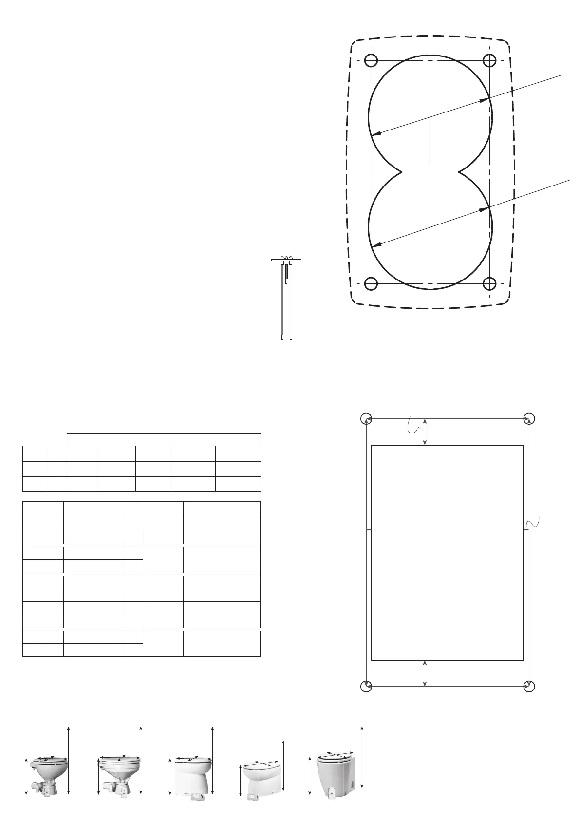
Ø 45 (1¾”)
Ø 45 (1¾a”)
Drill 2 slightly overlapping 45 mm holes in the
mounting surface to acommodte the electronics.
Drill 4 appropriate sized holes for your preferred
fasteners to secure the switch panel to its mounting
surface.
Scale 1:1
Scale 1:1
H
W
L
H
H
W
L
H
H
W
L
H
W
L
H
W
L
Silent Electric Compact Silent Electric Comfort Premium Electric Standard Premium Electric Low Design Silent Electric
3
Control Panel
Rocker Switch
(07-66-025)
Template
Digital Control
Panel
(07-66-024)
Template
78 x 55 mm (3.1 x 2.2 in)
Rectangle to be cut out of
the mounting surface, at
least 26 mm (1.1 in) deep,
for the electronics.
2 mm (0.08 in)
9.5 mm (0.37 in)
97 mm (3.8 in)
59 mm (2.3 in)
 Loading...