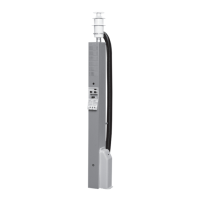
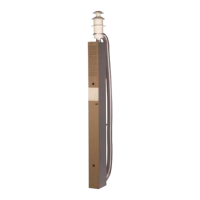
BOILER INSTALLATION
The best place for the boiler is in a
wardrobe or storage space, but it can also
be located under the fl oor of the vehicle.
If located outside the vehicle, the boiler
should be built into an enclosed space
so that it is protected from water spray,
exhaust fumes, etc. In choosing the loca-
tion, also bear in mind the need to be able
to remove the service panel (A 1) and that
room should be left for replacement of
components during servicing.
The rating plate on the boiler must be
legible after installation.
The fi tting dimensions given in Fig. A are
recommended
minimum dimensions when fi tting the
boiler.
The space where the boiler is to be fi tted
must be ventilated, with a ventilation area
of at least 70 cm
2
.
The boiler must be screwed securely to
the fl oor through the holes in the fi xing
brackets (A 2).
NB! The boiler must not be located in the
passenger area of a vehicle of type M2
or M3.
Fig. A
1. Service panel
2. Holes for fi xing with screws
FITTING A ROOF FLUE
The boiler may only be fi tted with the origi-
nal fl ue. The fl ue must not be blocked.
The roof fl ue should be mounted on a
level surface (a roof pitch of 30º maximum
is however acceptable). No items may be
mounted on the roof within a radius of 200
mm from the fl ue.
Mark the hole centre where the fl ue is
to be mounted and drill a Ø 76 mm hole
through the roof. Fit the fl ue, working
from outside the roof. Seal between the
mounting washer (C 4) and roof (C 5) with
an automotive body sealant, and screw
the fl ue securely in place with six fl athead
self-tapping screws (C 6).
Fit the fl ue, working from outside the
roof. Seal between the mounting washer
(C 4) and roof (C 5) with an automotive
body sealant, and screw the fl ue securely
in place with six fl athead self-tapping
screws (C 6).
These instructions deal with the instal-
lation and assembly of the boiler and
expansion tank. Read these instruc-
tions carefully before fi tting the boiler.
These instructions are approved for the
Alde Compact 3020 boiler fi tted in cara-
vans, motor caravans or buildings in
accordance with CE 0402 no. SC0653-13
and have the E5 mark for installation in
vehicles in accordance with ECE R122,
no. 00 001 and R10, no. 04 166.
Installation and repairs may only be car-
ried out by a specialist. Always comply
with national regulations.
TECHNICAL DATA
Measurements/Weight
Boiler height: 310 mm
Boiler width: 340 mm
Boiler length: 510 mm
Weight: 14 kg (without fl uid)
Gas: Propane
Butane
Output Stage 1: 3.3 kW 3.8 kW
Consumption: 245 g/h 275 g/h
Output Stage 2: 5.5 kW 6.4 kW
Consumption: 405 g/h 460 g/h
Pressure: I
3+
28-30/37 mbar
I
3B/P
30 mbar
Volume/Pressure/Temp.
Volume of liquid, radiator water: 3.5
litres
Volume of liquid, domestic hot water:
8.4 litres
Maximum pressure, radiator water:
0.05 MPa (0.5 bar)
Maximum pressure, domestic hot
water: 0.3 MPa (3.0 bar)
System temperature: 85°C max.
230–240 V
Output, element: 1 x 1050 W
(2 or 3 kW) 1 x 2100 W
12 V DC
Power consumption: 1 amp (max.)
Fuse: 3.15 amp+/3.15 amp-
FITTING A WALL FLUE
The boiler may only be fi tted with the ori-
ginal fl ue. The fl ue must not be blocked.
In choosing the location, bear in mind that
there must always be adequate ventilation
of exhaust gases into the open air.
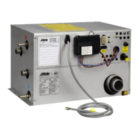
The wall fl ue should be mounted on as
fl at a surface as possible, allowing air to
circulate freely past the fl ue. There must be
a minimum lateral distance of 200 mm from
any projecting item.
There must be a minimum lateral distance
of 300 mm from a window that can be
opened or a ventilation air intake. The fl ue
must not be mounted under a window that
can be opened or a ventilation air intake;
see drawing.
If the fl ue is fi tted at a distance which is
closer than indicated above, a window
circuit-breaker switch must be installed
that shuts off the LPG gas supply when
the window is opened. To ensure the boiler
works as intended, no item should be fi tted
within a radius of 300 mm around the fl ue
(not a legal requirement).
REMEMBER to always comply with cur-
rent national regulations.
The distance from the fl ue to a ventilation
air intake under the vehicle should be at
least 300 mm (not a legal requirement).
The distance from the fl ue to a fi lling point
or ventilation for fuel must be at least 500
mm.
Mark up where the fl ue is to be located.
Then drill a Ø 83 mm hole through the
outer wall. First fi t the gasket (B 7), and
then screw the fl ue (B 8) securely in place
with the six fl athead self-tapping screws (B
9). If the surface is of contoured type, such
as hammered sheet metal, an automotive
body sealant must be used around the
gasket.
Note that the fl ue must be fi tted with the
elbow pointing upwards, (the roof fl ue is
also marked TOP OBEN). Then fi t the
plastic cap (B 10a) and the O-ring (B 10b),
using the two screws (B 11) supplied.
INSTALLATION INSTRUCTIONS – COMPACT 3020
Window
Prohibited zone