EasyManua.ls Logo

Alderon Industries Power Post PPMS-0001 - User Manual

Alderon Industries Power Post PPMS-0001
4 pages
Print Icon
To Next Page IconTo Next Page
Loading...
QUICK START GUIDE
Power Post
Monitoring System
Pump Connection Center | Demand Dose, Integrated Alarm
15 Amp, 120/240VAC | Models: PPMS-0001 and PPMS-0002
Safety Guidelines
Step 2: Remove Bottom Cover Step 4: Installing Wire into WAGO
Before proceeding with the installation or operation of this product,
read all instructions thoroughly, as well as complying with all federal,
state and local codes, regulations, and practices. This product must
be installed by qualied personnel familiar with all applicable local
electrical and mechanical codes. Refer to the National Electrical Code
(NFPA 70). Failure to properly install and test this product can result in
personal injury or equipment malfunction.
WARNING
Step 1: Install Post
QSG00291_Rev07_PPMS_Power Post Monitoring System | May 27, 2022 2:03 PM
Before making wire connections and terminations, carefully read this
step for proper functions of both types of WAGO connectors.
WARNING: Improper use of the connectors will cause damage, DO
NOT use mechanical tools to open or close, hand usage only.
Wire Termination - Splice Connector WAGO (Fig. 1):
1) Lift tab(s) upward.
2) Insert wire(s) into slot.
3) Press tab(s) downward.
4) Make sure wire(s) are secured.
Wire Connection - Quick Snap Terminal WAGO (Fig. 2):
1) Press tab(s) outward. DO NOT open past 40° angle
2) Insert wire(s) into slot.
3) Press tab(s) inward.
4) Make sure wire(s) are secured.
Determine location for the post in the
ground near a tank and drill access
holes for the float switch cables using
the customer supplied conduit/fittings or
Alderons riser connection kit. Route the
cables through access holes and wire as
described in step 5. Run the direct burial
power wires underneath the bottom of
the post as shown in the diagram.
Note: Seal all conduits to prevent moisture and gases
from entering the post per local codes.
Direct
Burial
Wires
2B2A
Remove the bottom enclosure cover screw, slide directly downward
until the sound chamber is cleared (2A) and pull directly away (2B).
Step 3: Remove / Install Post Cap
Remove Post Cap:
1) Remove Screws and Lift Cap Upwards
Install Post Cap:
1) Position text FRONT (with arrows) Forward
3) Align Fastener Holes
4) Fasten Screws to Secure Cap to Post
(Fig. 1) (Fig. 2)
TO OPEN
WAGO
TO CLOSE
WAGO
TO OPEN
WAGO
TO CLOSE
WAGO
FRONT
Alderon Industries™ | Patent Pending
Question and Answer IconNeed help?

Do you have a question about the Alderon Industries Power Post PPMS-0001 and is the answer not in the manual?

Summary

Power Post Monitoring System Overview

Safety Guidelines and Warnings

Crucial safety instructions and warnings before installation and operation.

Step 1: Install Post

Instructions for determining location and installing the post.

Step 2: Remove Bottom Cover

Procedure to remove the bottom enclosure cover for access.

Step 3: Remove; Install Post Cap

Guide on how to remove and install the post cap.

Step 4: Installing Wire into WAGO Connectors

Detailed instructions for proper use of WAGO connectors for wiring.

Installation and Wiring Steps

Step 5: Wiring and Piggyback Plug Connections

Detailed wiring instructions and piggyback plug connection.

Step 6: Testing Procedures

Comprehensive testing steps for all system functions and alarms.

Step 7: Install Bottom Cover

Instructions for reinstalling the bottom enclosure cover.

Step 8: Backfill

Procedure for backfilling the area around the post and wiring.

Menu System Navigation

Main Menu - Blank Screen State

Description of the screen behavior when the system is idle.

Main Menu - System Normal State

How to access the main menu from the system normal state.

Resettable History Menu

Accessing and navigating event statistics for resettable history.

Settings Menu

Accessing and configuring system settings, including password.

Lifetime History Menu

Accessing and navigating event statistics for lifetime history.

Model;Firmware Menu

Accessing information about the system model and firmware.

Product Features and Specifications

Power Post Monitoring System Features

Detailed explanation of each feature and indicator on the system.

Included with Product

List of components included in the product package.

Customer Support Information

Contact details and resources for customer support.

Specifications

Technical specifications for the Power Post Monitoring System.

Model Number Nomenclature

Explanation of the model number designation.

Overview

The Alderon Industries™ Power Post™ Monitoring System (Models: PPMS-0001 and PPMS-0002) is a pump connection center designed for demand dose and integrated alarm applications. It operates at 15 Amp, 120/240VAC and is patent pending.

Function Description:

The Power Post™ Monitoring System serves as a central hub for controlling and monitoring pump operations, integrating alarm functions, and providing a user interface for system settings and statistics. It manages power to the pump, monitors various conditions through float switches and sensors, and alerts users to potential issues via visual and audible alarms. The system is designed for outdoor installation, with features to protect internal components from environmental factors.

Important Technical Specifications:

  • Pump Power Receptacle: 120VAC or 240VAC, 15A, 60Hz.
  • Pump Power: 120VAC or 240VAC, 13A or 15A, 60Hz (voltage/amps depend on model/part number).
  • Alarm Power: 120VAC, 60Hz (240VAC, 60Hz available; consult factory).
  • Power Consumption: 14 Watts maximum (alarm condition).
  • Enclosure: Outdoor, rated Type 3R.
  • Certifications: FCC Part 15 (US/Canada), CSA (US/Canada).
  • Included with Product: (1) Power Post™ junction box and cable grips pre-installed on post, (1) Pre-installed, female, 15A, pump power receptacle (voltage depends on model/part number), and (2) Wago connectors.

Usage Features:

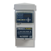
The Power Post™ features an OLED Display Screen that shows system functions and LED indicators. It includes a Menu Keypad for toggling system functions, programming settings, and viewing statistics. A Test/Silence Pushbutton provides quick access to lifetime pump run event counter statistics, testing or silencing the alarm, or exiting the menu system.

Wiring and Connections:

The system utilizes quick snap terminal blocks for fast and easy connections. It supports two power sources for the pump and alarm, as well as connections for a filter switch and a high-level alarm float switch. Direct burial power wires are routed underneath the post. The system includes a pre-installed female power receptacle for piggyback plug connections. WAGO connectors are used for secure wire terminations.

User Interface and Menu System:

The menu system is accessed via arrow keys and a MENU button. It includes:

  • Main Menu - Blank Screen: Appears when the system is idle; pressing any arrow key wakes the system to "SYSTEM NORMAL."
  • Main Menu - System Normal: The default screen; pressing MENU accesses the main menu.
  • Main Menu - Resettable History: Displays event statistics such as Pump Run Stats, Extended Pump Run Stats, High Amp Stats, Pump Float Stats, High Level Alarm Stats, Filter Alarm Stats, Pump Fail Stats, and Power Loss Stats. These statistics can be cleared and are retained during power outages.
  • Main Menu - Settings: Allows access to system settings, protected by a password (factory set to 1919). Settings include Normal LED Setting (On/Off), Pump Run LED Setting (On/Off), Silence Time Setting (up to 24 hours), Extended Pump Run Time Setting (up to 30 minutes), High Amp Level Setting (up to 15 Amps), and Gallons Per Minute Setting (factory set to Zero).
  • Main Menu - Lifetime History: Displays non-resettable lifetime statistics for the same categories as Resettable History, providing a permanent record of system performance.
  • Main Menu - Model/Firmware: Displays the device's model and firmware version.

Alarm and Indication Features:

  • Power On Indicator: Green LEDs illuminate inside the top cover, can be disabled in settings.
  • Alarm Beacon: Multi-colored LEDs (red, amber) illuminate for various alarm conditions.
  • Pump Run Indicator: Blue LEDs illuminate inside the top cover, can be disabled in settings.
  • System LED Indicators: Multiple color indicators provide visual feedback for system events and alarm conditions.
  • Alarm Buzzer: Annunciates to indicate an alarm event.
  • Sound Chamber: Maximizes buzzer output and protects it from water intrusion.

Maintenance Features:

  • Testing: The system provides a comprehensive testing procedure, including:
    • TEST ALARM LEDs and BUZZER: Verifies alarm functionality and displays lifetime pump run event counter statistics.
    • TEST ALARM FLOAT SWITCH: Activates the alarm float switch to test red LEDs and buzzer.
    • TEST ALARM SILENCE: Silences the buzzer while the alarm float switch is active.
    • TEST FILTER SWITCH: Activates the filter switch to test amber LEDs and buzzer.
    • TEST PUMP AND PUMP FLOAT SWITCH: Requires water in the tank; activates the pump float switch to test blue LEDs and display pump run event and amps.
  • Recommended System Settings: Alderon™ recommends changing factory settings for high amp level, extended pump run time, and gallons per minute to customize the system per application.
  • Test Weekly: Users are advised to test the product once a week to ensure proper functioning.

Installation Features:

  • Post Installation: The post is designed for direct burial, with access holes for float switch cables and direct burial power wires. Conduits should be sealed to prevent moisture and gases.
  • Removable Bottom Cover: Allows access for wiring and maintenance.
  • Removable/Installable Post Cap: Secures the top of the post and allows airflow while preventing gas/condensation buildup.
  • Cable Grips: Pre-installed for easy and secure cable installation.
  • Backfill: The area around the post, riser, and direct burial power wiring should be backfilled after installation and testing.

Alderon Industries Power Post PPMS-0001 Specifications

General IconGeneral
BrandAlderon Industries
ModelPower Post PPMS-0001
CategoryMeasuring Instruments
LanguageEnglish

Related product manuals