3-2
ENGLISH
Description
MODBUS protocol manual
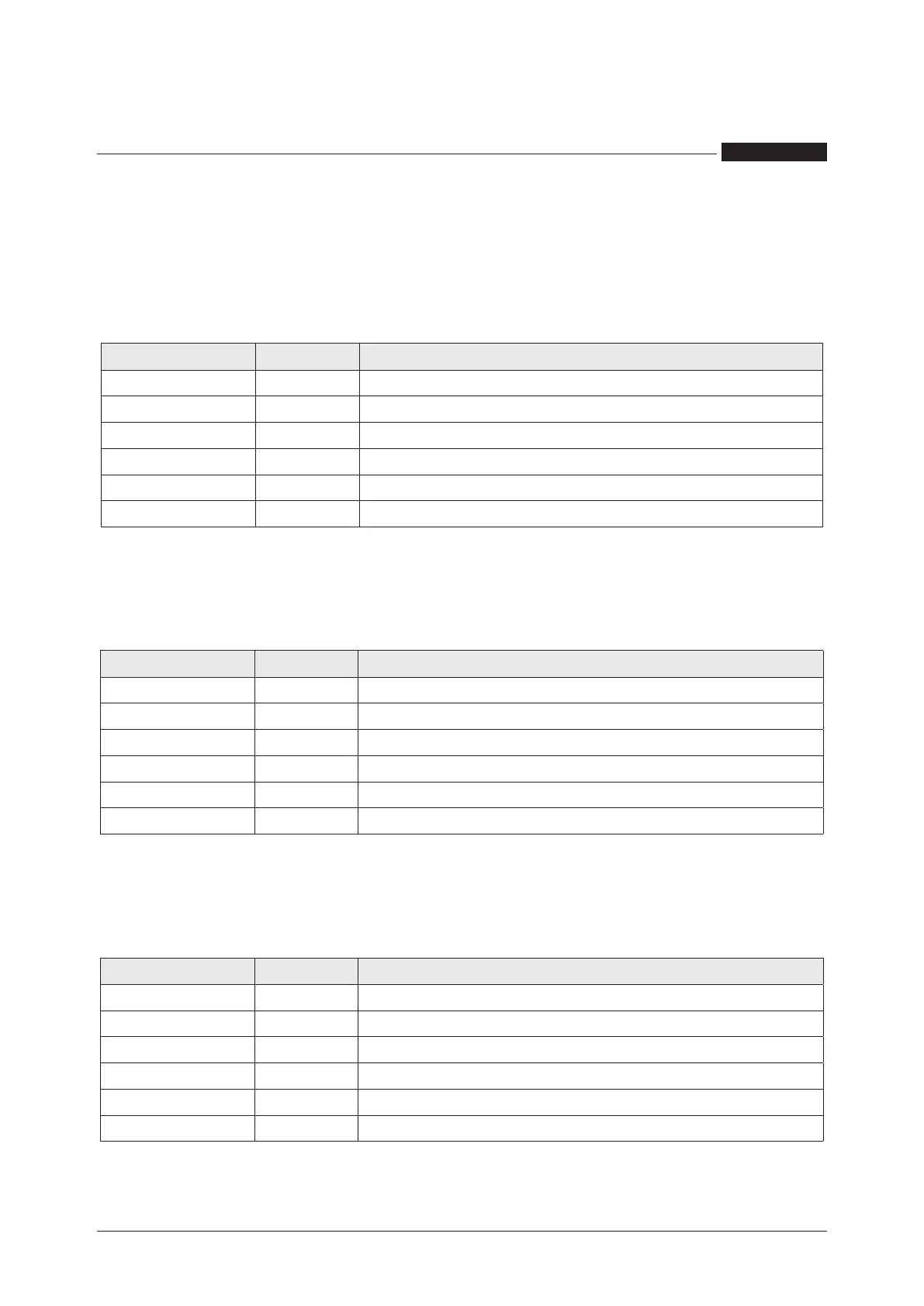
COMMUNICATION FRAME STRUCTURE
ASCII mode
Bit per byte: 1 Start, 7 Bit, Even, 1 Stop (7E1)
Name Length Function
START FRAME 1 char Message start marker. Starts with colon “:” ($3A)
ADDRESS FIELD 2 chars Instrument logical number
FUNCTION CODE 2 chars Function code ($03=read command, $10=write command)
DATA FIELD n chars Data + length will be filled depending on the message type
ERROR CHECK 2 chars Error check (LRC)
END FRAME 2 chars Carriage return - line feed (CRLF) pair ($0D & $0A)
RTU mode
Bit per byte: 1 Start, 8 Bit, None, 1 Stop (8N1)
Name Length Function
START FRAME 4 chars idle At least 4 character time of silence (MARK condition)
ADDRESS FIELD 8 bits Instrument logical number
FUNCTION CODE 8 bits Function code ($03=read command, $10=write command)
DATA FIELD n x 8 bits Data + length will be filled depending on the message type
ERROR CHECK 16 bits Error check (CRC)
END FRAME 4 chars idle At least 4 character time of silence between frames
TCP mode
Bit per byte: 1 Start, 7 Bit, Even, 2 Stop (7E2)
Name Length Function
TRANSACTION ID 2 bytes For synchronization between messages of server & client
PROTOCOL ID 2 bytes Zero for MODBUS TCP
BYTE COUNT 2 bytes Number of remaining bytes in this frame
UNIT ID 1 byte Slave address (255 if not used)
FUNCTION CODE 1 byte Function code ($03=read command, $10=write command)
DATA BYTES n bytes Data as response or command
 Loading...
