3-4
ENGLISH
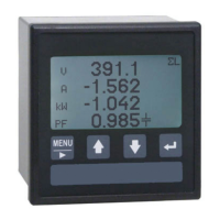
Description
MODBUS protocol manual
3.2 CRC generation
The Cyclical Redundancy Check (CRC) field is two bytes, containing a 16–bit value. The CRC value is
calculated by the transmitting device, which appends the CRC to the message. The receiving device
recalculates a CRC during receipt of the message, and compares the calculated value to the actual
value it received in the CRC field. If the two values are not equal, an error results.
The CRC is started by first preloading a 16–bit register to all 1’s. Then a process begins of applying
successive 8–bit bytes of the message to the current contents of the register. Only the eight bits of
data in each character are used for generating the CRC. Start and stop bits, and the parity bit, do
not apply to the CRC.
During generation of the CRC, each 8–bit character is exclusive ORed with the register contents. Then
the result is shifted in the direction of the least significant bit (LSB), with a zero filled into the most
significant bit (MSB) position. The LSB is extracted and examined. If the LSB was a 1, the register is
then exclusive ORed with a preset, fixed value. If the LSB was a 0, no exclusive OR takes place.
This process is repeated until eight shifts have been performed. After the last (eighth) shift, the
next 8–bit character is exclusive ORed with the register’s current value, and the process repeats for
eight more shifts as described above. The final contents of the register, after all the characters of
the message have been applied, is the CRC value.
A calculated procedure for generating a CRC is:
1. Load a 16–bit register with $FFFF. Call this the CRC register.
2. Exclusive OR the first 8–bit byte of the message with the low–order byte of the 16–bit CRC regi-
ster, putting the result in the CRC register.
3. Shift the CRC register one bit to the right (toward the LSB), zero–filling the MSB. Extract and
examine the LSB.
4. (If the LSB was 0): Repeat Step 3 (another shift).
(If the LSB was 1): Exclusive OR the CRC register with the polynomial value $A001 (1010 0000
0000 0001).
5. Repeat Steps 3 and 4 until 8 shifts have been performed. When this is done, a complete 8–bit
byte will have been processed.
6. Repeat Steps 2 through 5 for the next 8–bit byte of the message. Continue doing this until all
bytes have been processed.
7. The final contents of the CRC register is the CRC value.
8. When the CRC is placed into the message, its upper and lower bytes must be swapped as de-
scribed below.
PLACING THE CRC INTO THE MESSAGE
When the 16–bit CRC (two 8–bit bytes) is transmitted in the message, the low-order byte will be
transmitted first, followed by the high-order byte.
For example, if the CRC value is $35F7 (0011 0101 1111 0111):
Addr Func Data
Count
Data Data …. Data CRC
lo F7
CRC
hi 35
 Loading...
