EasyManua.ls Logo

Algodue ELETTRONICA UPM307 - User Manual

Algodue ELETTRONICA UPM307
24 pages
Print Icon
To Next Page IconTo Next Page
Loading...
UPM307
UNIVERSAL POWER METER
USER MANUAL
1. INTRODUCTION
This manual provides information on the installation, configuration and use of the main instrument functions.
The manual is not intended for general use, but for qualified technicians.
This term indicates a professional and skilled technician, authorised to act in accordance with the safety
standards relating to the dangers posed by electric current.
This person must also have basic first aid training and be in possession of suitable Personal Protective
Equipment.
WARNING!
It is strictly forbidden for anyone who does not fulfill the above-mentioned requirements
to install or use the instrument.
The instrument complies with the European Union directives in force, as well as with the technical standards
implementing these requirements, as certified by the CE mark on the device and on this Manual.
Using the meter for purposes other than intended ones, understood by the manual content, is strictly
forbidden. The information herein contained shall not be shared with third parties. Any duplication of this
manual, either partial or total, not authorised in writing by the Manufacturer and obtained by photocopying,
duplicating or using any other electronic means, violates the terms of copyright and is punishable by law.
Any brands quoted in the publication belong to the legitimate registered owners.
NOTE. This manual describes the use of the main instrument functions.
1MAUXX307018

Other manuals for Algodue ELETTRONICA UPM307

Question and Answer IconNeed help?

Do you have a question about the Algodue ELETTRONICA UPM307 and is the answer not in the manual?

Algodue ELETTRONICA UPM307 Specifications

General IconGeneral
BrandAlgodue ELETTRONICA
ModelUPM307
CategoryMeasuring Instruments
LanguageEnglish

Summary

UPM307 User Manual Introduction

Manual Purpose and Target Audience

Defines the manual's intent for qualified technicians and safety precautions.

Graphic Symbols and Product Description

Device Warning Symbols

Explains symbols indicating high voltage, serious damage, or minor damage risks.

Product Overview and Configuration

Describes the UPM307's capabilities, display, and standard configuration.

Initial Product Verification

Unboxing and Damage Check

Instruction to check the instrument for damage upon unboxing.

Installation and Environmental Requirements

Installation Environmental Conditions

Specifies environmental conditions for instrument installation.

Physical Mounting Procedure

Details the physical mounting procedure, including hole dimensions and accessory use.

Safety Measures and Electrical Connections

Critical Safety Warnings

Critical warnings regarding high voltage and the need for skilled personnel.

Electrical Connection Safety Checklist

Essential safety checks before making any electrical connections.

Power Switch Off Precaution

Crucial warning to ensure the main switch is OFF before connecting.

Communication Port Setup: Serial

RS232 and RS485 Serial Interfaces

Details RS232 and RS485 serial interfaces for PC connectivity.

Communication Port Setup: LONBUS

FTT-10 LONBUS Port Configuration

Describes the LONBUS port connection, service pin, and diagnosis LED.

Communication Port Setup: PROFIBUS

PROFIBUS Cable and Termination

Covers cable requirements, termination, and connector pinouts.

PROFIBUS Signal Definitions

Explains the signals used on the PROFIBUS interface.

PROFIBUS Network Address Setup

Details setting the network address using rotary switches.

PROFIBUS Multi-Master System Warning

Warning about potential issues in multi-master PROFIBUS systems.

Communication Port Setup: ETHERNET

Ethernet Port Indicators and Pinout

Explains LED indicators, port pinout, and their meanings.

Ethernet Configuration Parameters

Lists default IP address, subnet mask, gateway, and serial settings.

Digital Output Configuration and Safety

Digital Output Power Disconnection

Critical safety warning to disconnect power before handling digital outputs.

Digital Output Wiring and Protection

Provides guidelines for connecting digital outputs and notes on overload protection.

PNP and NPN Wiring Examples

Illustrates wiring for PNP and NPN digital output configurations.

Voltage and Current Input Wiring

3-Phase System Wiring Configurations

Illustrates connections for various 3-phase configurations with CTs.

Rogowski Coil Connection Note

Specific instruction for connecting Rogowski coils.

Additional Voltage and Current Input Wiring

3-Phase, 3-Wire, 1 CT Wiring

Wiring diagram for 3-phase, 3-wire, 1 CT setup.

3-Phase, 2-Wire, 1 CT Wiring

Wiring diagram for 3-phase, 2-wire, 1 CT setup.

Single-Phase Wiring Diagram

Wiring diagram for single-phase setup.

Power Supply and Input Specifications

Voltage and Current Input Details

Details input voltage and current parameters, impedance, and burden.

Power Supply Versions and Wiring

Lists available power supply versions and recommended fuse installation.

Power Supply Connection Warning

Warning to check network voltage correspondence before connecting the instrument.

Instrument Operation: Control Panel and Startup

Control Panel and Button Functions

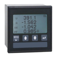
Explains the front LCD display and pushbutton functions.

Instrument Initialization and Startup

Details the power-on sequence, info display, and wiring mode check.

Wiring Mode Verification Alert

Crucial note to verify connections match the programmed wiring mode.

Menu Navigation and Setup Access

General Menu Structure Overview

Overview of main menu sections: Instantaneous, Setup, Info, etc.

Setup Menu Access and Sections

Lists main configuration sections: Main, Communication, Digital OUT, Utility Setup.

Setup Page Exit Options

Available choices for exiting setup pages and saving changes.

Main Configuration Settings: PT, CT, Wiring

Voltage and Current Transformer Ratios

Sets the primary to secondary ratios for voltage and current transformers.

CT Ratio Warning for Rogowski Inputs

Warning about changing CT value for Rogowski inputs to avoid incorrect current readings.

Current Input Range and Wiring Mode

Selects current input range and available wiring configurations.

Wiring Mode Verification

Emphasizes checking wiring diagram correspondence with the actual wiring.

Communication Configuration Settings

Demand Time and Protocol Selection

Sets demand integration time and communication protocol.

Baud Rate, Mode, and Address

Configures communication speed, data format, and address for serial ports.

Digital Output Configuration Details

Digital Output Variable and Mode Settings

Sets output mode (PULSE, HIGH, LOW) and associated parameters like delay and hysteresis.

Pulse Value Calculation for Energy

Explains how to calculate pulse values for energy measurements.

Utility Setup Options: Contrast, Clear, Language

LCD Contrast Adjustment

Adjusts the LCD contrast level.

Clearing Counters and Peak Values

Options to clear energy counters and DMD/Peak values.

Backlight and Language Settings

Configures backlight timeout and display language.

Utility Setup Procedures and Pushbutton Functions

Procedure for Clearing Counters

Detailed steps and choices for clearing energy counters.

Procedure for Clearing DMD & Peak Values

Detailed steps and choices for clearing DMD & Peak values.

Pushbutton Operation for Setup Changes

Step-by-step guide for using pushbuttons to set or modify setup values.

Menu Structure and Navigation

General Menu Flow Diagram

Visual representation of the instrument's menu structure and navigation flow.

Configuration Verification and Maintenance

Troubleshooting Phase and PF Issues

Troubleshooting steps for negative phase signs and incorrect PF values.

Troubleshooting Power Value Inconsistencies

Troubleshooting steps for inconsistent power readings.

Instrument Maintenance

Cleaning Guidelines

Guidelines for cleaning the display and keyboard using appropriate materials.

Technical Specifications Overview

Power Supply and Input Specifications

Details power supply voltage, current, and voltage input parameters.

Communication, I;O, and Environment

Lists specifications for communication ports, digital outputs, and environmental conditions.

Performed Measurements and Data Storage

Instantaneous Measurement Parameters

Lists all instantaneous electrical parameters measured by the instrument.

Stored Data Types

Lists stored energy and peak value data categories.