9
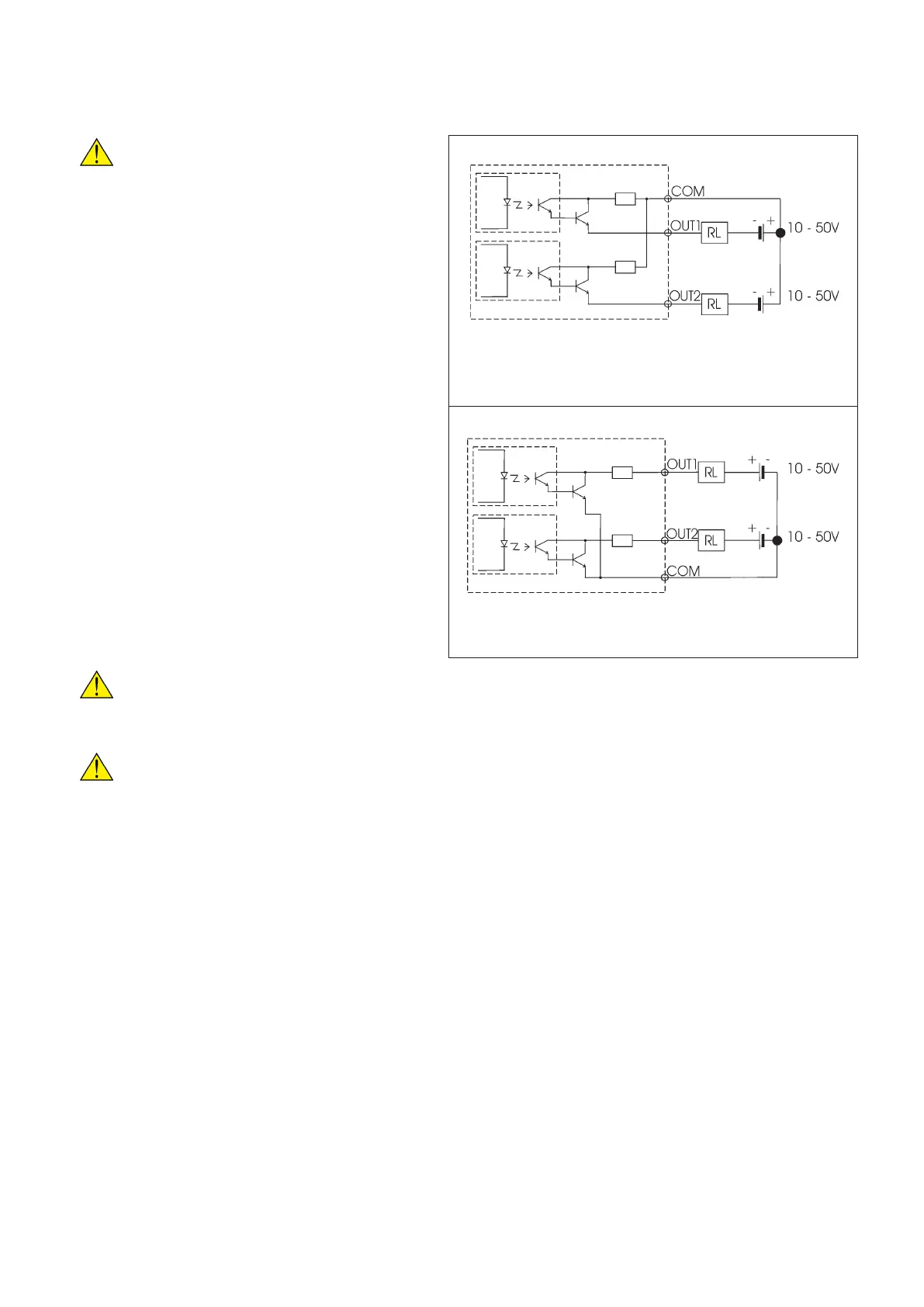
A) PNP wiring
B) NPN wiring
7.5 DIGITAL OUTPUTS
The instrument is equipped with two digital outputs. The digital outputs can be programmed for alarm
tripping or energy pulse emission.
WARNING!
Before connecting or disconnecting
the digital outputs, be sure that the
instrument is not powered. The power
supply line, the measurement inputs
and any other voltage source must be
disconnected.
7.5.1 Digital outputs connection
For short distance electrical connections use
normal single or multi-polar cables. For longer
connections, the signal cables must not lie close
to the power supply wires. If the signal cables and
power supply wires cross, keep a right angle (90°)
to limit the magnetic field. The needed function is
programmed through instrument setup.
Maximum withstandable voltage: 50 VDC
Maximum load current: 100 mA
WARNING!
On request, the unit is supplied with the digital outputs for wiring A (PNP) or B (NPN). Refer
to the label on the back of the meter in order to identify its configuration.
WARNING!
The outputs are not protected against overloads and short-circuits.
 Loading...
