8
8
7
6
5
4
3
2
1
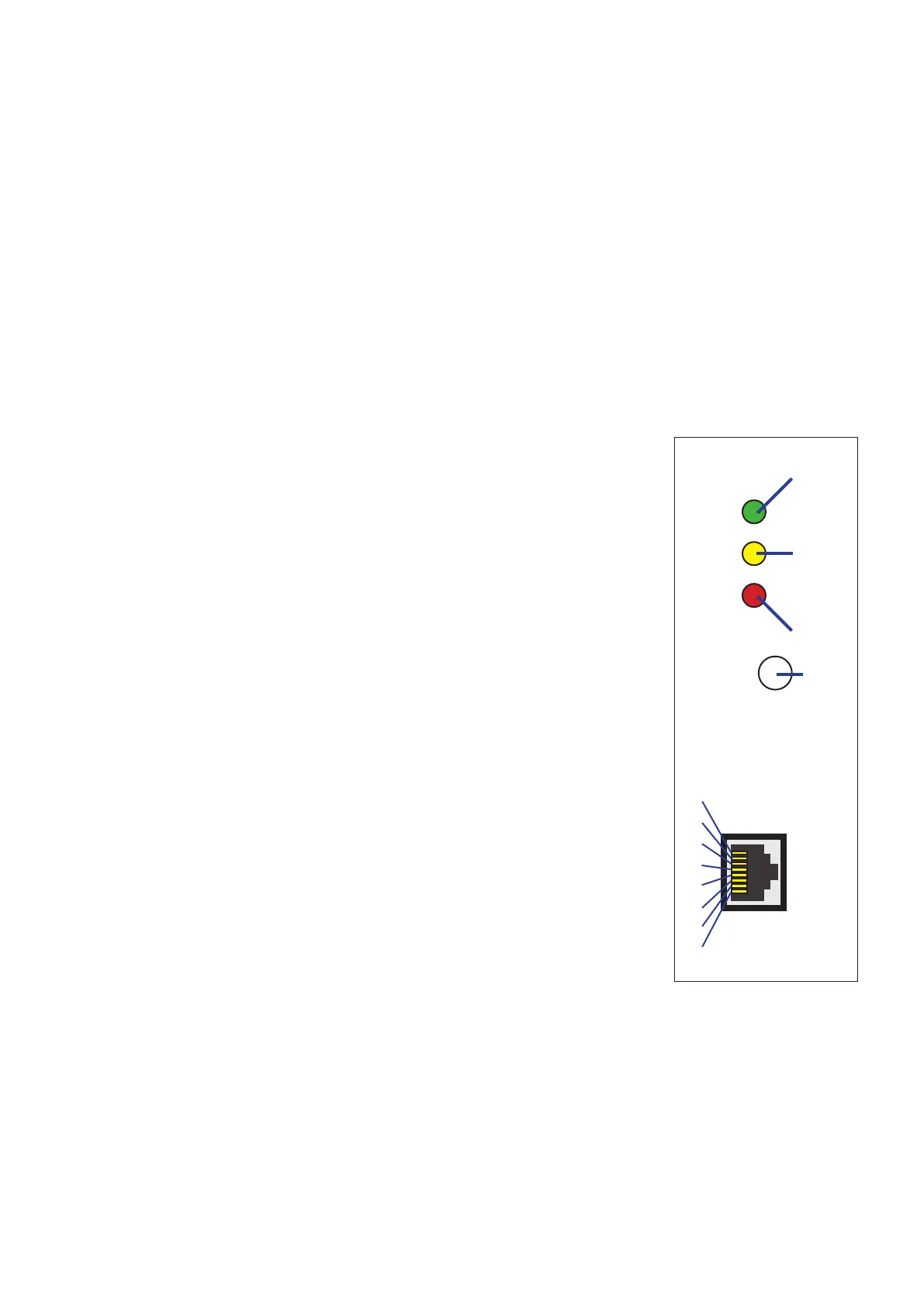
10/100
LINK
ERR
RESET
7.4 ETHERNET COMMUNICATION PORT (optional)
The ETHERNET interface allows a connection between the instrument and an ETHERNET network. For the
connection use an HUB or a Switch. If the instrument is set on STANDARD protocol and it is connected to
the network, all instrument measurements can be displayed remotely on a PC by typing the IP address of
the instrument ETHERNET interface in the web address field.
10/100 (green LED) Indicates the communication speed.
LED ON=100 Mbit/s•
LED OFF=10 Mbit/s•
LINK (yellow LED) Indicates link status.
LED ON=link OK•
BLINKING LED=link activity•
ERR (red LED) According to the LED operation, it can indicates:
LED ON=an error occurred in ETHERNET interface or ETHERNET •
interface boot phase
BLINKING LED=parameters restore in progress•
The following list describes the pin meaning of the ETHERNET port.
Pin. Meaning
1 Tx+
2 Tx-
3 Rx+
4 Not used
5 Not used
6 Rx-
7 Not used
8 Not used
The ETHERNET configuration is as follows:
IP Address = 192.168.1.253•
Subnet Mask = 255.255.255.0•
Gateway = 192.168.1.1•
Listen Port = 3000•
Serial Option = 57600,N,8,1•
To change the ETHERNET configuration, refer to the ETHERNET interface User
Manual.
LAN
port
 Loading...
