12
WARNING!
Check that:
1. if the instrument must carry out bi-directional measurements to obtain correct measurements, the
connections must respect the polarities.
2. the connections are made according to the diagrams in the following section, respecting the cyclic order
of phases (important: L1 of the voltage input = L1 of the current input)
3. when voltage or current transformers (PT / CT) are used, in the input and output polarities must be
respected.
4. before disconnecting current input the load power supply is cut off.
If this is not possible, the secondary CT must be short-circuited.
7.6.1 Voltage specifications
The standard voltage specifications are listed below:
NOTE. The label on the meter defines the real configuration.
Input voltage 600 (750) VAC L-L
Input impedance ›1.3 MOhm
Load max 0.15 VA per phase
7.6.2 Current specifications
The phase and polarity of the input current are an essential parameters for a proper instrument operation.
The stardard current specifications are listed below:
NOTE. The label on the meter defines the real configuration.
Rated input current 1 or 5A, programmable
Input impedance approx. 0.02 Ohm
Load max 0.5 VA per phase
Isolation max 150Vrms between phases
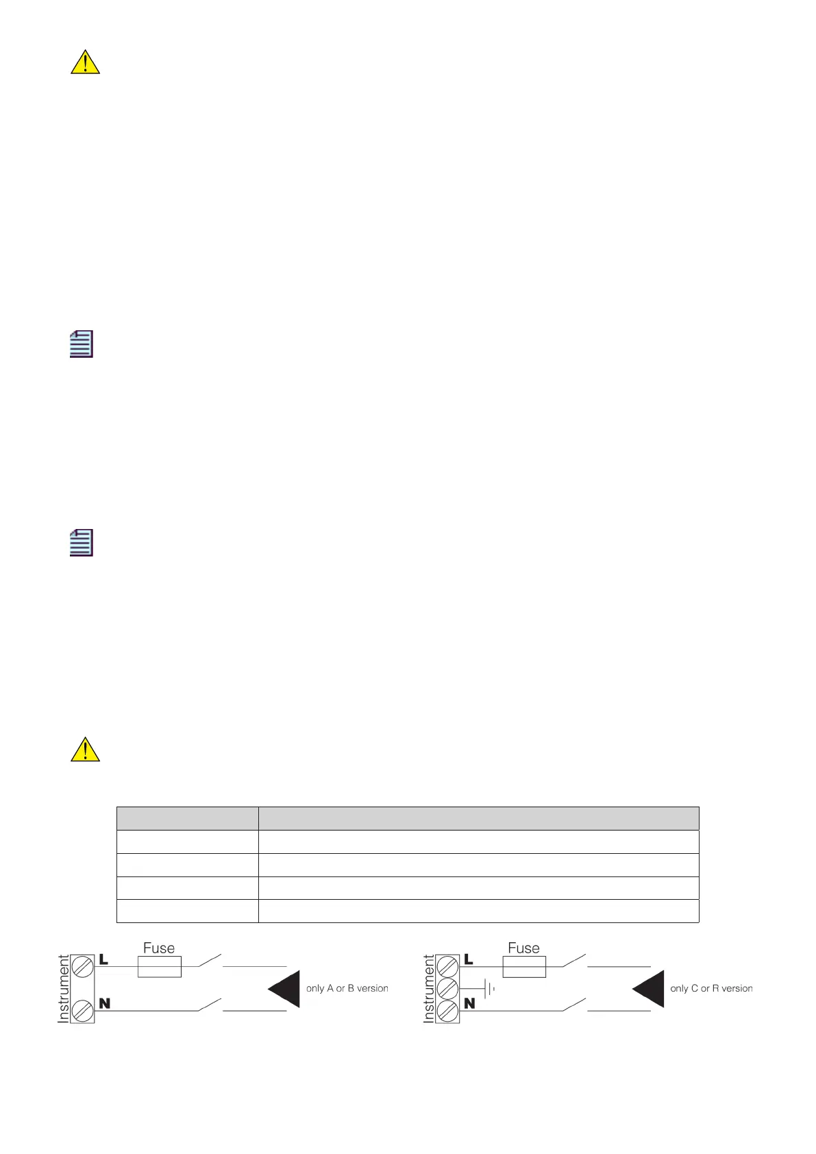
7.7 POWER SUPPLY
Connect the power supply to the L and N terminals on the back side.
WARNING!
Before connecting the instrument to the network, check that the network voltage corresponds
to the value on the label.
Version Power supply
A 115 V
AC
+15% -20%
B 230 V
AC
+15% -20%
C 65÷250 V
AC
/ 90÷250 V
DC
R 19÷60 V
DC
It is recommended to install an external 315mA fuse (or equivalent protection circuit) as well as a switch
on power supply terminals.
 Loading...
