ASSEMBLY INSTRUCTIONS
STEP 4
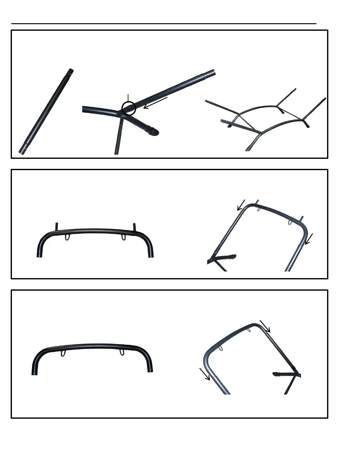
Locate the 4 upright pieces (Part E). Place either end of part E into part B of the base, through the
plastic joint protector part D, making sure the lock pin on part E fully engages in the lock-pin hole.
Part E E
D
B
Step 4 Completed
STEP 5
Locate the head end stand support (Part F). Choose either end of the base and slip Part F onto
the 2 part E uprights making sure the lock-pins fully engage the lock-pin holes.
Part F
E
E
F
STEP 6
Locate the foot end stand support (Part G). Slip part G onto opposite 2 uprights part E making
sure the lock-pins fully engage the lock-pin holes.
Part G
G
E
E