③ When we need output 5V from USB-A interface, or use a mouse (wired and wireless) to control the
device, please set the USB-A interface to the host mode (USBH), then connect the mouse/mouse wireless receiver.
First do not move the mouse, then roll the mouse wheel until the device emits a beeping sound (when the mouse
wheel is detected), the left, middle, right buttons and the scroll wheel of the mouse correspond to the 3 buttons and
scroll wheel of DP100 one-to-one, and the functions are the same (after shutdown or switching to slave mode, the
mouse control is invalid ).
4.2.2 Operation instructions
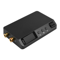
Click the middle button ■ to enter the parameter setting state, click ■ again to switch the
output voltage setting and constant current setting cyclically,After the parameter bit is highlighted,
click the or to move the parameter highlight position left or right, and then adjust the
highlighted value by scroll wheel, as shown in Figure 4.2.2:
Figure 4.2.2 Parameter setting
After the parameter adjustment is completed, you can long press any key to exit the
parameter setting. Timeout (8Sec) automatically exited parameter setting.
In the parameter setting state, the functions of the buttons and the scroll wheel are shown in
Table 4.2.1:
Table 4.2.2 Button function
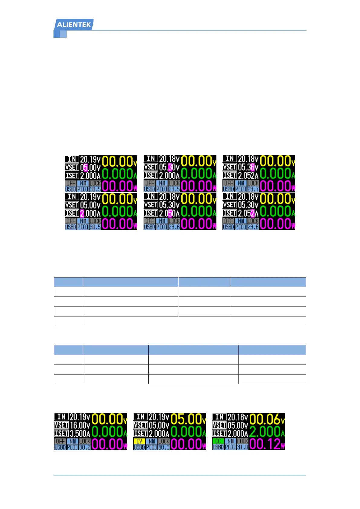
Change output mode, including OFF mode, constant voltage mode CV and constant current
mode CC, as shown in Figure 4.2.3:
Figure 4.2.3 Output mode
 Loading...