ALIMAK 34824 - 1 /01
A 45
Installation
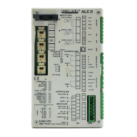
During erection of the lift – assembling mast sections, mast ties,
landing enclosures etc, turn the Norm. / Insp. switch to position
”Insp”. The lift is then manually controlled from the Inspection
push-buttons on the car roof.
Commissioning
All electrical equipment in the car is installed and wired at the
factory. It's a ’’ready to use package’’ requiring no further
assembly. The remaining installation of the system is performed
at the job site according to the following:
1. Install incoming power cable to the B panel in accordance
with the wiring diagram.
2. Install cable(s) between B panel and the car in accordance
with the wiring diagram.
3. Adjust the reference (retardation down) cam on the mast.
4. Check that all cams are correctly installed on the mast, both
on top and bottom, by travelling manually in the Inspection
mode.
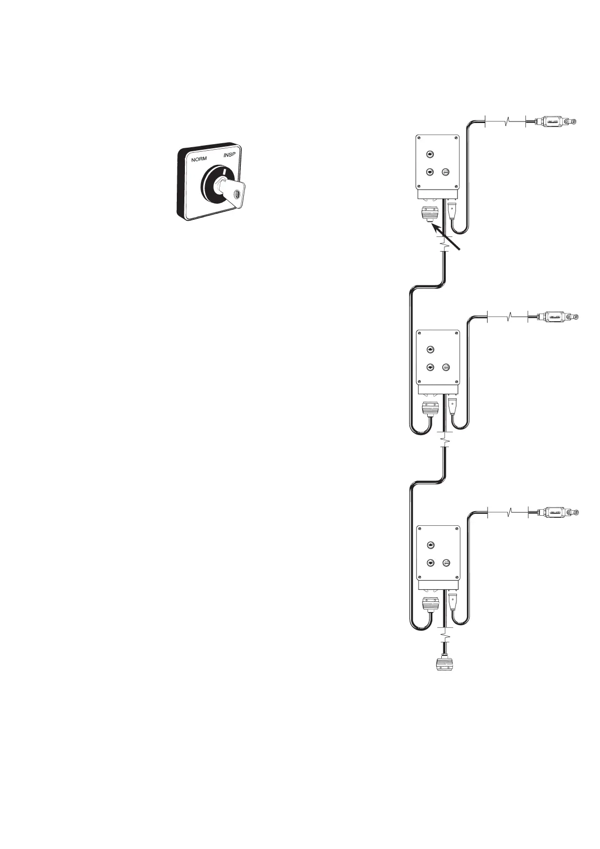
5. Connect the landing control cable to the base panel and to
each landing unit in accordance with the wiring diagram.
6. The system is now ready for programming.
Prefabricated
push-button
box
Landing door
monotoring
electric switch
By-passed plug to be
installed at the top
landing to accomplish
the landing circuit
Plug for connection
of the landing circuit
to the B-panel
 Loading...