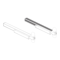
This manual describes the Allegion Size 2-6 Adjustable Backcheck Closer and the Size 2-6 Adjustable Backcheck & Delayed Action Closer. These devices are designed for pull-side regular application (Fig. 1), push-side parallel arm application (Fig. 66), and push-side transom application (Fig. 61), accommodating door openings up to 180°, subject to hinge and surrounding structure limitations.
Function Description:
The door closers are mechanical devices designed to control the closing speed and latching action of a door. They feature adjustable power settings, backcheck, and in some models, delayed action, to ensure smooth and controlled door closure. The backcheck function provides resistance when the door is opened past a certain point, preventing the door from slamming into the frame or wall. The delayed action feature holds the door open for an extended period before it begins to close, which can be useful for accessibility or moving objects through the doorway.
Important Technical Specifications:
Closer Power Sizes (Fig. 1, Fig. 61):
The closers offer six adjustable power sizes, each corresponding to a maximum door weight and width:
- #1: 20kg max door weight, 750mm max door width.
- #2: 60kg max door weight, 950mm max door width.
- #3: 40kg max door weight, 850mm max door width.
- #4: 80kg max door weight, 1100mm max door width.
- #5: 100kg max door weight, 1250mm max door width.
- #6: 120kg max door weight, 1400mm max door width.
Closer Power Sizes (Fig. 66 - Parallel Arm Application):
For parallel arm applications, the power sizes are slightly different:
- #1: 20kg max door weight, 750mm max door width.
- #2: 60kg max door weight, 950mm max door width.
- 3: 40kg max door weight, 850mm max door width.
- 4: 80kg max door weight, 1100mm max door width.
- 5: 100kg max door weight, 1250mm max door width.
Adjustable Features:
- LATCH SPEED: Controls the speed of the door during the final few degrees of closing, ensuring proper latch engagement.
- DOOR SPEED: Controls the main closing speed of the door.
- BACKCHECK: Provides hydraulic resistance when the door is opened forcefully beyond a certain point (typically 70-80 degrees), preventing damage to the door, frame, or wall.
- DELAY: (For Backcheck & Delayed Action Closer models only) Controls the duration the door remains open before the closing cycle begins.
Factory Set Power (Fig. 1):
The closers are factory set to size 4, with 0 turns for power adjustment.
- Size 2: -6 turns (approx)
- Size 3: -3 turns (approx)
- Size 4: 0 turns (approx)
- Size 5: +6 turns (approx)
- Size 6: +12 turns (approx)
Factory Set Power (Fig. 61 - Transom Application):
The closers are factory set to size 3, with 0 turns for power adjustment.
- Size 1: -6 turns (approx)
- Size 2: -3 turns (approx)
- Size 3: 0 turns (approx)
- Size 4: +3 turns (approx)
- Size 5: +8 turns (approx)
- Size 6: +12 turns (approx)
Factory Set Power (Fig. 66 - Parallel Arm Application):
The closers are factory set to size 3, with 0 turns for power adjustment.
- Size 1: -6 turns (approx)
- Size 2: -4 turns (approx)
- Size 3: 0 turns (approx)
- Size 4: +4 turns (approx)
- Size 5: +10 turns (approx)
Usage Features:
Installation Procedures:
The manual outlines detailed installation steps for three primary applications:
-
Pull Side - Regular Application (Fig. 1):
- Step 1: Peel templates off backing paper, position on door/frame, and pilot drill 6 holes.
- Step 2: Fit mechanism bracket (2 screws) and arm bracket assembly (2 screws).
- Step 3: Fit main arm assembly to mechanism (90° angle) and securely tighten fixing screw with spanner.
- Step 4: Locate mechanism assembly on bracket and secure (2 screws). Peel off templates.
- Step 5: Open door to engage secondary arm strip and tube. Close door and set secondary arm at 90° to door face. Securely tighten clamp bolt with spanner.
- Step 6: Adjust power and door speeds as necessary.
- Step 7: Fit cover to closer following steps shown (2 screws).
-
Push Side - Parallel Arm Application (Fig. 66):
- Step 1: Mark out door/frame as detailed overleaf and pilot drill 8 holes.
- Step 2: Fit mechanism bracket (2 screws) and arm bracket assembly to Fig. 66 bracket (2 screws). Fit bracket assembly to frame (4 screws).
- Step 3: Fit main arm assembly to mechanism (45° angle) and securely tighten fixing screw with spanner.
- Step 4: Fully close door speed and latch regulators. Pull main arm forward. Locate mechanism assembly on bracket and secure (2 screws).
- Step 5: Open door to engage secondary arm strip and tube. Close door and set main arm parallel to door face. Securely tighten clamp bolt with spanner.
- Step 6: Adjust power and door speeds as necessary.
- Step 7: Fit cover to closer following steps shown (2 screws).
-
Push Side - Transom Application (Fig. 61):
- Step 1: Mark out door/frame as detailed overleaf and pilot drill 6 holes.
- Step 2: Fit mechanism bracket (2 screws) and arm bracket assembly (2 screws).
- Step 3: Fit main arm assembly to mechanism (90° angle) and securely tighten fixing screw with spanner.
- Step 4: Locate mechanism assembly on bracket and secure (2 screws).
- Step 5: Open door to engage secondary arm strip and tube. Close door and set secondary arm at 90° to door face. Securely tighten clamp bolt with spanner.
- Step 6: Adjust power and door speeds as necessary.
- Step 7: Fit cover to closer following steps shown (2 screws).
Adjustment:
Adjustments for latch speed, door speed, backcheck, and delay (if applicable) are made via screws on the closer body. The manual provides diagrams for identifying these adjustment points. Power adjustment involves turning a screw, with specific turns corresponding to different power sizes.
Safety Warning:
Door closer power #1 & #2 and those supplied with mechanical hold-open devices must not be installed on fire/smoke doors.
Maintenance Features:
Quarterly Maintenance:
- Lubrication: Periodically apply light oil to arm knuckle joints and door hinges.
- Inspection: Check that the door closer closes the door correctly and that all fixing screws are tight.
Optional Covers:
The closers can be fitted with standard or optional covers, which are secured with two screws, as shown in the final step of the installation process.
All dimensions provided in the manual are in millimetres.