Do you have a question about the Allegion LCN Benchmark AU9100 Series and is the answer not in the manual?
| Finish | Aluminum |
|---|---|
| Closing Speed | Adjustable |
| Backcheck | Adjustable |
| Release Time | Adjustable |
| Series | AU9100 Series |
| Mounting Type | Surface |
| Handing | Universal |
| Mounting | Surface Mount |
| Compatibility | Standard Doors |
Identifies the Allegion brand and the LCN Benchmark AU9100 Series Low Energy Operators.
Provides the title and date of the installation manual.
Describes the LCN Benchmark 9100 Series as an automatic electromechanical swing door operator.
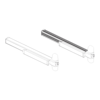
Illustrates and names the pull arm and track assembly and the push arm assembly.
Diagram showing basic parts for the 9100 Series Benchmark door operator.
List of replacement parts for the 9130 Series, specific to ANCLR/ANDKB models.
List of replacement parts for the 9140 Series, specific to ANCLR/ANDKB models.
Diagrams detailing required clearances for pull system installations.
Diagrams detailing required clearances for push system installations.
Specifies 240 Volt, 60 Hz fused supply requirements and dedicated circuit needs.
Instructions for preparing the header and door for pull system installation.
Instructions for preparing the header and door for push system installation, including reveal dimensions.
Safety precautions for routing wires and using copper conductors.
Details connecting ground, Hall effect, motor power, and control box power cables.
Guidance on connecting activate, safety, key switch, and lock accessories.
Procedure for attaching the operator arm loosely with an 8-mm socket head screw.
Steps for attaching the arm to the door, including push arm shoe.
Details for sliding the pull arm roller into the track and attaching it to the door.
Instructions for adjusting the arm length to align the door at 90 degrees.
Describes the automatic sizing cycle performed after activation.
Checks for door binding, lock disengagement, and electrical connections.
Verifying door movement, speed adjustments, and safety device functionality.
Details key features like opening speed, back check, hold open time, and latch position.
Explains the function and control for various operator adjustments.
Ensures removal of tools, debris, and installation of safety labels.
Instructs owner on proper operation, inspection, and maintenance.
Informs owner on whom to contact for service and maintenance.
Covers sizing, auto reverse, and standard operation modes.
Details standard, lock-only, and fire alarm function selections.
Provides a chart mapping program numbers to operational functions.
Instructions for configuring control box settings.
Presents wiring diagrams for the LCN AU9100.
Diagrams showing adjustment for opening speed, back check, latch position, and more.
Illustrates the function selector dial for choosing operating modes.
Configuration options for power boost duration and Push N Go activation.
Diagrams for J4 Top and J4 Bottom terminal blocks with labeled connections.
Illustrates wiring for different keyswitch positions (OFF, 1 Way, 2 Way, HO).
Shows wiring connections for the motor and encoder.