GR05 User Guide 19
External Ducking Trigger
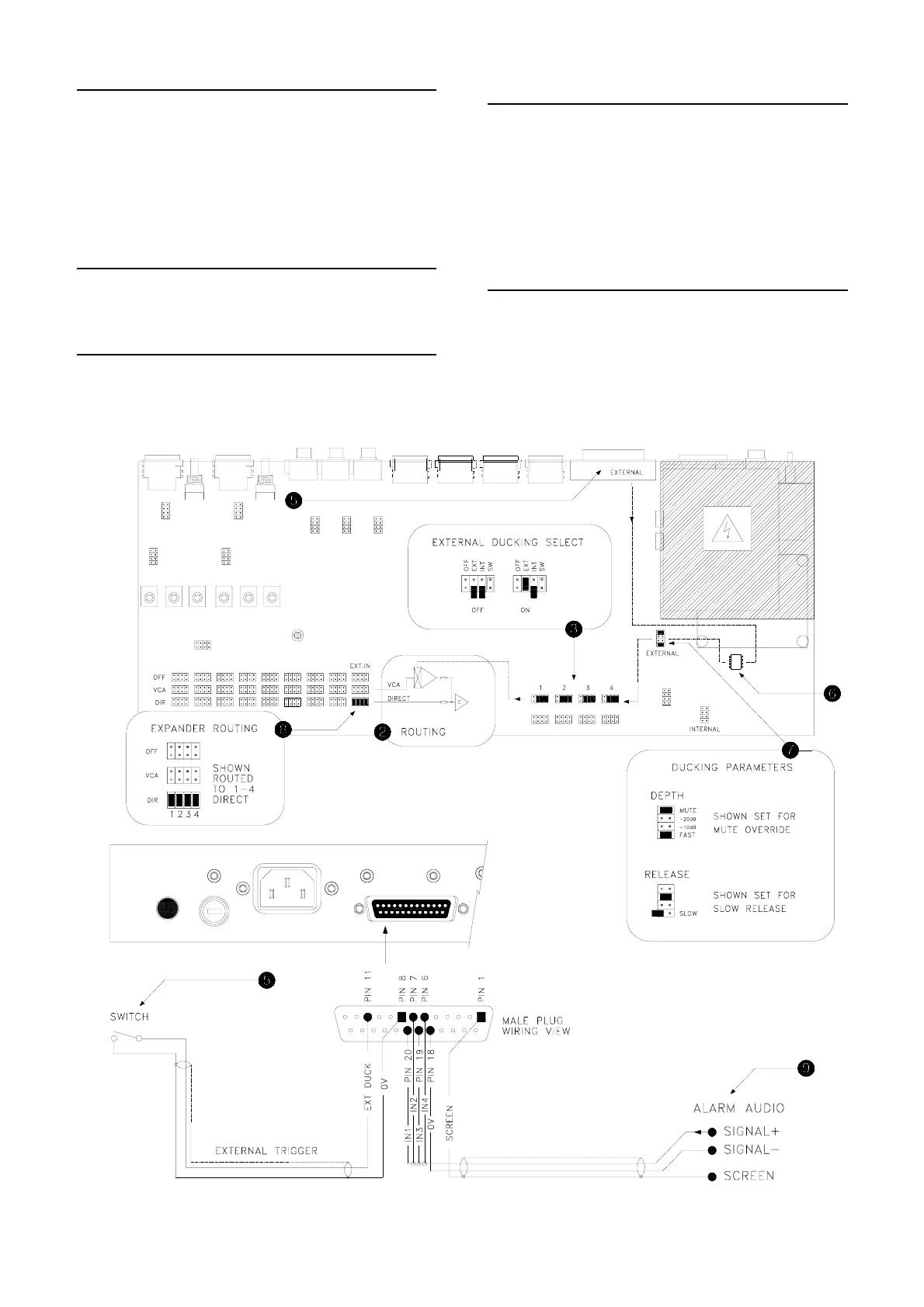
External ducking is triggered by linking Pin 11 of the
expander / remote connector to Pin 8 (0V ground). Wire
these pins to a switch or relay. Closing the switch
contacts triggers ducking.
Equipment such as alarm and jukebox systems often
provide trigger outputs suitable for direct connection to
these pins.
Opto-Isolated Input
The external ducking trigger input is opto-isolated
(coupled) to avoid interference from external controllers.
External Ducking Parameters
Set the depth and release link options as shown. For
alarm override and jukebox replay the recommended
settings are depth = MUTE (off), release = SLOW.
Expander Routing
The expander input provides an additional input to each
of the outputs via either the VCA or DIRECT signal paths.
To interface to an alarm system set the routing to
DIRECT so that the alarm signal is not affected by level
control or ducking. You could route a different
evacuation message to each zone if required. Use the
external ducking input to mute the music when the alarm
is triggered.
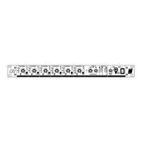
Expander Connector
The wiring example shows the alarm signal connected to
expander inputs 1 to 4. Shield the audio signal by
connecting the cable screen to Pin 1 as shown.
EXPANDER / REMOTE
 Loading...