Do you have a question about the ALLEN & HEATH GR05 and is the answer not in the manual?
Details the conditions required for warranty coverage.
Guidance on correctly wiring the mains plug for safe operation.
Precautions regarding mains supply settings and adequate unit ventilation.
Guidelines for operating environment, protecting from moisture, and cleaning.
Important notes regarding audio connection types and safety.
Instructions for mounting the GR05 unit in a rack or on a desk/shelf.
Guidance on connecting the unit using various pluggable connectors.
How to configure front panel controls for operator use or lockout.
Procedure for safely removing the unit's top cover for internal adjustments.
Details on setting up microphone and line inputs, including EQ and routing.
Details on setting output levels, EQ, and VCA/Direct routing.
How to configure output level controls and the ducking system.
Final steps for checking and completing the unit installation.
Steps for mounting the GR05 into a standard 19-inch rack case.
Instructions for setting up the GR05 for desktop or shelf placement.
Ensuring correct mains voltage and understanding the input cable.
Information on the mains fuse, its replacement, and the power switch.
Connecting an external DC power supply or battery for backup.
Explanation of power status LEDs and the importance of earthing.
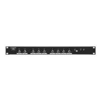
Level controls and signal meters for microphone/line inputs.
Level controls and post-level signal meters for zone outputs.
Setting front panel level controls for operator use, preset, or lockout.
Description of signal meters, mute, ducking, and power status indicators.
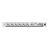
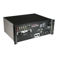
Location of the IEC mains input, fuse, and power switch.
Details of the 3-pin male XLR impedance balanced output connectors.
Description of RCA phono and XLR connectors for line and microphone inputs.
The 25-pin D-type connector for expansion and remote control functions.
Location and function of the rear panel gain trimmer for mic inputs.
How to connect microphones and line sources via XLR, including unbalanced options.
Setting gain trim and using the 30dB attenuator pad for microphone inputs.
Enabling phantom power and the low-cut filter for microphone inputs.
Adjusting mid/high and low frequency EQ for microphone inputs.
Configuring signal paths (VCA or DIRECT) and illustrative routing examples.
Description of RCA sockets and setting input sensitivity for line inputs.
Configuring signal routing for stereo line inputs to various outputs.
Details of XLR connectors and setting output signal levels.
Adjusting EQ and monitoring output levels using LED meters.
Explanation of VCA and DIRECT signal paths for zone outputs.
Configuring front panel or remote DC control for output levels.
Enabling/disabling the mute switch and selecting affected outputs.
Details of the 25-pin D-type connector and the +10V DC reference.
Using potentiometers or external systems for remote level control.
Setting which outputs are controlled by remote DC voltage.
Selecting mic triggers and routing signals for internal ducking.
Enabling internal, external, or both ducking types per output.
Configuring ducking depth and release time for internal triggers.
Using external triggers and setting parameters for external ducking.
Routing expander inputs for alarms and connector details.
Using the expander connector for output signals instead of XLRs.
Connecting multiple GR05 units to increase input capacity.
Details on system features, input types, and electrical characteristics.
Data on output capabilities, frequency response, distortion, and noise.
Physical dimensions and weight of the GR05 unit.
| Channels | 5 |
|---|---|
| Line Inputs | 3 |
| Outputs | 2 |
| Stereo Zones | 1 |
| EQ on Mic Input | Yes |
| Phantom Power | Yes |
| Aux Sends | 1 |
| Headphone Output | Yes |
| Power Supply | Internal |
| EQ | 2-band |