EasyManua.ls Logo

ALLEN & HEATH GR1 - User Manual

ALLEN & HEATH GR1
17 pages
Print Icon
To Next Page IconTo Next Page
Loading...
ALLEN&HEATH
GR1
24 Input 3 output Zone Mixer
USER GUIDE
(Installation)
PUBLICATION: AP2057
Question and Answer IconNeed help?

Do you have a question about the ALLEN & HEATH GR1 and is the answer not in the manual?

ALLEN & HEATH GR1 Specifications

General IconGeneral
BrandALLEN & HEATH
ModelGR1
CategoryMixer
LanguageEnglish

Summary

Introduction to GR1 Unit

Service and Technical Support Options

Critical Safety Warnings and Precautions

Audio Interconnection Guidelines

Optimizing Audio Signal Levels

Technical Specifications Overview

Detailed Input and Output Connections

Unit Installation Procedures

Power Supply and Backup Connections

Front Panel Control Functions

Input Channel Controls

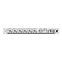
Details controls for signal level, pan, source selection, and peak indication.

Master Output and Monitoring Controls

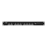
Covers alarm, limit indicators, monitor level, stereo/mono selection, and output meters.

Internal Configuration Options

Audio System Earthing and Grounding

Microphone Input Configuration

Covers gain calibration, phantom power, 20dB pad, and lo-cut filter settings.

Line Level Input Connections

Mono and Stereo Line Input Details

Explains 1/4" jack line inputs and how to set operating levels via jumpers.

Mono and Stereo Aux Input Connections

Details AUX inputs on the SYS-LINK connector for additional line sources.

Channel Direct Output Configuration

Direct Output PRE;POST Setting

Configuration for setting direct outputs to pre or post channel level control.

Channel to Output Routing

Channel Routing Jumper Settings

Selects inner/outer jumper links for routing signals to outputs L, R, and M.

SYS-LINK I;O for System Expansion

Main Output Configuration

Main Output Level Setting

Sets operating levels for the main L, R, M outputs via jumper links.

Output XLR Ground Lift Option

Manages XLR pin 1 connection to audio 0V for grounding and loop avoidance.

Priority Ducking System Operation

Channel Ducking Disable

Allows disabling ducking for individual channels via jumper link settings.

Ducking Effect Configuration

Sets the amount of signal reduction and the time for signal recovery.

Compressor and Limiter Functions

Limiter Sidechain Source Selection

Determines the source signal that triggers the compressor/limiter action.

Compression Ratio Settings

Configures the ratio of input change to output change for compression.

Stereo Link for Compressors

Enables linked operation of compressor/limiters for stereo signals.

Compressor;Limiter Threshold Adjustment

Adjusts the signal level at which the compressor/limiter starts to engage.

Remote Level Control Options

Internal vs. External Control Selection

Configures VCA control to use internal front panel or external DC voltage.

+10 V DC Voltage Source Selection

Selects the source for the +10V DC reference voltage for remote control.

Alarm Override System

Alarm Audio Source Selection

Selects between external alarm input or local MIC 6 for alarm audio.

Alarm Audio Test Function

Allows testing of the alarm audio path without activating the override.

Expanding Inputs via SYS-LINK

SYS-LINK Input Expansion Wiring

Details connecting GR1 units using SYS-LINK to expand input channel capacity.

Expanding Outputs via SYS-LINK

SYS-LINK Output Expansion Wiring

Describes connecting DIR outputs to AUX inputs for expanding output feeds.

Related product manuals