Do you have a question about the ALLEN & HEATH iDR-4 and is the answer not in the manual?
Configuration of the iDR-4 hardware for audio processing.
Details on warranty terms and conditions for product defects.
General guidance to follow safety and operating instructions.
Warning against opening the unit; refer service to qualified personnel.
Connecting to mains power, ground connection, and power cord usage.
Ensuring airflow, avoiding heat sources, and protecting from environmental factors.
Advice on preventing damage during handling, transit, and installation.
Instructions for wiring mains plugs correctly, including earth, neutral, and live wires.
Guide intended for technical engineers for installation and configuration.
Reference to iDR System Manager Help file and product support via website.
Explanation of how the guide is structured and symbols used.
Introduction to the iDR system and its components like iDR-4.
Details on connecting expanders, networked control, and remote options.
Features of iDR-4, iDR-in, iDR-out, and iDR-switch units.
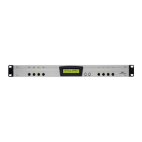
Overview of front panel controls, LEDs, LCD display, and soft keys.
Features of iDR System Manager, PL Designer, Client software, and processing.
Details on matrix, stereo linking, configurations, channel processing, and signal generator.
Details on rack ears, rubber feet, label slots, and face plate fixing.
Description of the LCD display and soft LEDs.
Description of soft keys, MENU, ESC, ENTER, and scroll keys.
Description of link, lock, and soft LEDs on expander units.
Mains input, Network port, and Port Active Indicators.
RS232 (MODEM), SysNet, PL-Anet, and DR-Link ports.
Audio inputs, outputs, monitor I/O, and expander ports.
Switch closure inputs, logic outputs, and earth terminals.
Overview of iDR-4's 6 inputs/outputs and expandability to 14x14.
Diagram illustrating the unexpanded iDR-4 system architecture.
Description of hardware audio connections like XLR, TRS, and digital expanders.
Explanation of processing channels, source patchbays, and expander integration.
Details on iDR-4's XLR/TRS inputs/outputs and expander interfaces.
Information on ADC/DAC converters, expander ports, and monitor I/O.
Description of signal generator and source patchbays.
Description of the 16x16 crosspoint matrix for routing and level control.
Delay settings for output channels and metering options for signal monitoring.
PEQ, Gate, Compressor, Sidechain Filter, and Limiter for signal shaping.
Faders, mute, polarity, groups, stereo linking, and monitor bus.
Pager, Ducking, AMM, Level Sense Switching, and Naming.
List of all components included in the iDR-4 package.
Overview of the iDR System Manager software and installation process.
Advice to check the Allen & Heath website for the latest software version.
List and description of files provided with the software package.
Instructions for rack mounting, desk mounting, and face plate installation.
Advice on ensuring adequate ventilation and avoiding heat sources.
Diagrams showing dimensions for iDR-4, expanders, and iDR-switch.
Reasons for mains earth connection: safety and audio performance.
Recommendation for professional cables and advice on routing.
Using low impedance sources and balanced connections for immunity.
Information on IEC60065 and UL6500 compliance.
Recommendation for using UPS in installations where public safety is at risk.
Instructions for installing the iDR System Manager software and starting an offline session.
Reminder of safety instructions and checking mains supply compatibility.
Steps for turning the unit on and parameters restored on power-up.
How to check the current operating code version using the front panel.
Explanation of how operating code is stored and managed by boot code.
Required settings for HyperTerminal or alternative terminal programs.
Step-by-step guide for updating operating code via RS232 using HyperTerminal.
How to access and navigate the setup menus using front panel keys.
Patch Select, Clock, Unit Name, Network, PPP, Monitoring, Diagnostics.
Detailed steps on navigating and using the setup menus.
How to select and change the unit's name in the setup menu.
Using the Diagnostics menu to view IP, MAC, and connection status.
Methods for rebooting the iDR-4 after network or PPP setting changes.
How to test the hardware functionality without PC connection.
Explanation of signal meter colors and fader adjustment for unity gain.
Using setup menus to select expander patches for testing.
Steps for adjusting settings and preparing for PC connection.
Need to connect PC and set up front panel communication settings.
Using TCP/IP over Ethernet for fast and reliable configuration.
Using COM1 or COM2 RS232 for slower communication or modem interrogation.
Using TCP/IP via CAT5 Ethernet for PC communication.
Connecting directly to PC or via a network for system control.
Need for unique IP addresses and consulting network administrator.
Definitions of common networking terms like LAN, Ethernet, IP address, DHCP.
Connecting PC to iDR-4 using Ethernet and setting the MDI/X switch.
Manually assigning IP addresses and configuring PC IP settings.
Configuring iDR-4 network settings before connecting to a network.
Setting a unique unit name and obtaining the MAC address.
Plugging into network and configuring PC network settings.
Using the rear panel RS232 port for remote communication via modem.
Using RS232 for direct PC connection (slower than network).
Activating the RS232 port via the iDR System Manager.
Configuring iDR-4 and PC for dial-up connection using PPP settings.
Connecting iDR-4 to modem, dial-up process, and running iDR System Manager.
Connecting iDR-4 to PC via RS232, dial-up, and running iDR System Manager.
How to start the iDR System Manager and establish a connection.
Explanation of LINK and TX indicators for TCP/IP communication.
Setting time and day via front panel menus or iDR System Manager.
Storing system setup and patches as .cfg files for backup.
Recommendations for archiving configurations and using DEFAULT/RESET files.
Details on XLR inputs, phantom power, PAD, gain, and sensitivity.
Details on XLR outputs, maximum level, and connecting to line equipment.
How to adjust input gain and use the PAD for level control.
Description of TRS inputs 3-6 and their configuration for monitor use.
Description of TRS outputs 5-6 and their configuration for monitor use.
Default iDR-4 setup and reconfiguration for monitor functions.
Where monitor signals are available on TRS jacks 5 and 6.
Diagrams showing different iDR-4 configurations without expanders.
Options for configuring monitor settings in iDR System Manager.
Manually selecting monitor sources via front panel setup menu *7.
Using mouse movement to select monitor sources and ripple-through function.
Interconnecting monitor signals over distances and monitoring multiple units.
How expanders add analogue audio and connect via DR-Link.
Safety, grounding, powering, and status LED indications for expanders.
Using front panel setup menu *8 Diagnostics to check expander presence.
Diagram showing iDR-4 with input/output expanders and DR-Link connections.
Using CAT5 STP cable for expander connections up to 250 metres.
Connecting multiple iDR units via the 8-channel expander bus for flexible systems.
How units synchronize audio communication, master/slave roles, and status indicators.
Example diagram of two iDR-4 units chained with expanders and monitor bus.
Diagram showing two iDR-4 units with audio bus looped back.
Manually assigning a sync master unit in loop back systems via iDR System Manager.
Warning and advice on planning patches to avoid feedback.
Overview of the iDR-switch for switch closure inputs and logic outputs.
Connecting iDR-switch via DR-Link port using CAT5 STP cable.
Safety, grounding, powering, and status LED indications for the iDR-switch.
Advice on planning the system and configuring switch inputs/outputs.
Details on connecting external switches and logic to iDR-switch using terminals and grounding.
How switch inputs work via opto-coupling and linking to ground.
Description of opto-coupled open collector logic outputs and their power options.
Information on using remote control devices like PL wall plates with iDR-switch.
Selecting combinations of serial ports (RS232, SysNet, PL-Anet) via System Manager.
Specifications and uses for RS232, SysNet, and PL-Anet ports.
Explanation of non-volatile memory and how settings are retained or reset.
Role of boot code and operating code in unit functionality and updates.
Settings permanently held in the unit, not archived on PC.
Settings archived in .cfg files for specific installations.
Storing and recalling selected parameters in patches, including detailed lists.
Key to iDR flexibility, storing and recalling various settings.
Advice on planning system configuration and using simulation for experimentation.
Assigning controls and saving initial patches.
Saving only necessary parameters in working patches.
Examples like single key source selection and zone level change.
Front panel layout and overview of the iDR-4, iDR-in, iDR-out, and iDR-switch units.
Overview of rear panel connectors for all iDR units.
Overview of iDR system applications with iDR System Manager and PL Designer.
Diagram showing physical inputs, channels, matrix, outputs, and expanders.
Description of iDR-4, iDR-8, iDR-in, iDR-out, and iDR-switch units.
Description of iDR-4 operator/installer panels and expander front panels.
Details on DSP, latency, A/D, and D/A converters.
General performance specs like frequency response, crosstalk, THD+noise.
Detailed specs for the mic/line XLR and TRS line inputs.
Specs for line outputs and expander input/output ports.
Specs for stereo monitor inputs and outputs on TRS jacks 5 and 6.
Details on Network port and available communications port combinations.
Specifications for RS232, SysNet, and PL-Anet ports.
Specifications for DR-Link port and iDR-switch inputs/outputs.
Details on power supply, consumption, fuses, dimensions, and weight.
Details on iDR System Manager, PL Designer/Client, and software downloads.
Clock settings, naming conventions, and LCD display features.
Soft switches, soft LEDs, logic outputs, and PL remote controls.
Overview of memory, unit settings, configuration files, and patch parameters.
Source patchbays, mix matrix, level control, fader groups, and stereo linking.
PEQ, Gate, Compressor, Sidechain Filter, Limiter, and Delay for audio processing.
Stereo metering, AMM, Pager, and Signal Generator settings.
Default unit settings for name, network, PPP, and configuration parameters.
Default patch parameters for processing, routing, and front panel controls.
Instructions for creating custom labels for front panel keys and LEDs using a Word template.
| Output Channels | 8 |
|---|---|
| Bit Depth | 24-bit |
| A/D Resolution | 24-bit |
| Computer Connectivity | USB |
| Control Protocol | Ethernet |
| THD+N | <0.005% |
| Frequency Response | 20 Hz - 20 kHz |
| Rack Spaces | 1U |
| Type | Digital Audio Processor |
| Sample Rate | 48 kHz |
| EQ | 4-band parametric per channel |
| Dynamics Processing | Compressor per channel |
| Effects | Reverb, Delay |
| Dynamic Range | 110 dB |
| Power Supply | 100-240V AC |
| Weight | 6.5 lbs |