8 IDR-4 User Guide
Front Panel Overview
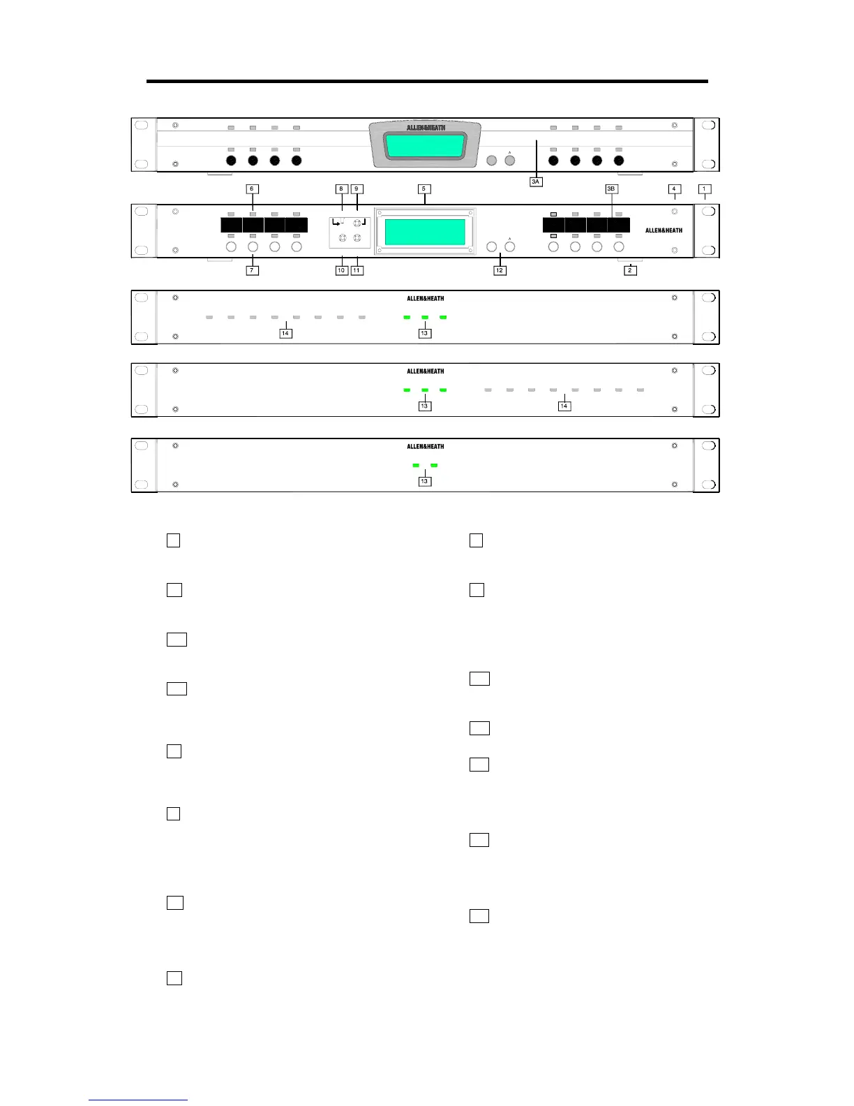
1 Rack ears Mount the unit into a standard 19”
equipment rack. Can be removed for stand alone
desk or shelf mounting.
2 Rubber feet Provided separately. Press
these into the base holes for stand alone desk or
shelf mounting.
3A Label slot A custom adhesive label can be
fitted here for operator identification of the soft key
and LED functions.
3B Write-on label blocks This is the installers
reference hidden by the face plate to mark up the
soft key, LED functions and other information
using a suitable marker pen or adhesive label.
4 Face plate fixing holes Fit the face plate
using the four M3 screws provided once the unit is
configured and labels fitted. A suitable 2mm hex
Allen key is supplied.
5 LCD display Displays system information on
a backlit 2x16 character LCD display. You can
configure this to display different combinations of
clock, patch name, unit name and user defined
text. It is also used to display the setup menu
items.
6 Soft LEDs 16 3-colour LED indicators
referred to as ‘soft’ because they can be assigned
by the installer as audio meters, mute, level
triggered, channel on or patch related indicators.
They can display red, green or yellow.
7 Soft keys 8 momentary action switches
which can be assigned by the installer as level,
mute or patch recall.
8 Code update switch Puts the unit into code
update mode ready to accept new operating code
from a PC. Status is shown on the LCD.
9 MENU key Press and hold this key for 2
seconds to access the setup menus. These let
you set up the clock, unit name, TCP/IP and PPP
communication parameters, select points in the
channel signal path to monitor, and check system
diagnostics and information.
10 ESC key Press this key to exit from the
displayed menu item and return to the previous
item or normal operation.
11 ENTER key Press this key to accept the
changes or navigate through the sub menus.
12 Scroll keys The U and V keys are used
when the soft keys are assigned as up/down level
controls. They are also used with the ESC and
ENTER keys to navigate through the setup
menus.
13 Expander status LEDs These display the
connection status. The ‘link’ LED lights when
communication is established via the DR-Link
port. The ‘lock’ LED lights when digital audio is
synchronised and working correctly.
14 Expander soft LEDs Can be assigned as
audio meters, mutes, level triggered or patch
related indicators in the same way as the main iDR
unit.
AUDIO INPUT EXPANDER
powerlock link
iDR-in
lock link power
AUDIO OUTPUT EXPANDER
iDR-out
link power
24 IN 16 OUT SWITCH CONTROLLER
iDR-switch
iDR-4
AUDIO MIX PROCESSOR
<
L1 L2 L3 L4
L10L9 L11 L12
S1 S2 S3 S4
L5 L6 L7 L8
L14L13 L15 L16
S5 S6 S7 S 8
ESC ENTER
MENU
hold for 2 sec
CODE UPDATE
<>
scroll
SETUP MENUS
iDR-4
AUDIO MIX PROCESSOR
<
 Loading...