Publication 1398-5.1 — January 2000
2-18 Install the ULTRA Plus PDM Components
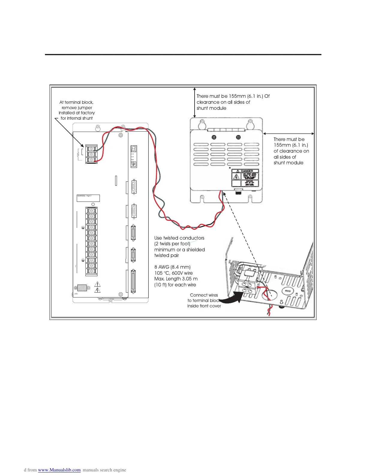
Figure 2.12
External Shunt (900W) mounting and connection diagram
!
"
#
$
%
&
'
)
*
+
,
-
.
WARNING: High Voltage
May Exist Up To Five Minutes
After Removing Power
DC Bus
DC Bus +
DC Bus -
L1
L3
L2/N
L1 AUX
L2/N AUX
T1B
EXTERNAL SHUNT
INTERNAL
SERIAL 2AUXILIARY
MOTOR ENCODER
CONTROLLER
SERIAL 1
J4
J3
J2
J1
J5
TB2
1
2
3
STATUS
COM
A2
A1
Motor
R
T
S
100-240 VAC 50/60 Hz
Use twisted conductors
(2 twists per foot)
minimum or a shielded
twisted pair
8 AWG (8.4 mm)
105 °C, 600V wire
Max. Length 3.05 m
(10 ft) for each wire
There must be 155mm (6.1 in.) Of
clearance on all sides of
shunt module
There must be
155mm (6.1 in.)
of clearance on
all sides of
shunt module
Cabinet
Connect wires
to terminal block
inside front cover
At terminal block,
remove jumper
installed at factory
for internal shunt

 Loading...


