Internally-mounted accessories are listed for field
installation under UL File E64983. Accessory instal-
lation should be done before the MCP is mounted
and connected. Refer to individual accessory
instruction leaflets.
To install the MCP, perform the following steps.
2-1. Make sure that the MCP is suitable for the intended
installation by comparing nameplate data with existing
ratings and system requirements. Inspect the MCP for
completeness, and check for damage before mounting.
Perform Steps 2-2, 2-3, and 2-4 only if installation of
internal accessories is required.
2-2. Remove cover screws and cover.
2-3. Install accessories.
WHEN REMOVED AND REINSTALLED, THREAD-
FORMING SCREWS WILL TRY TO REFORM THE
THREADS IN THE BASE. CARE SHOULD BE TAKEN
EVERY TIME A THREAD-FORMING SCREW IS USED
TO ENSURE THE SCREW STARTS IN THE ORIGI-
NAL THREADS. DAMAGED THREADS CAN RESULT
IN IMPROPER MCP COVER RETENTION.
2-4. Install cover and secure with pan-head screws, fol-
lowed by thread-forming screws, as shown in Fig. 2-1.
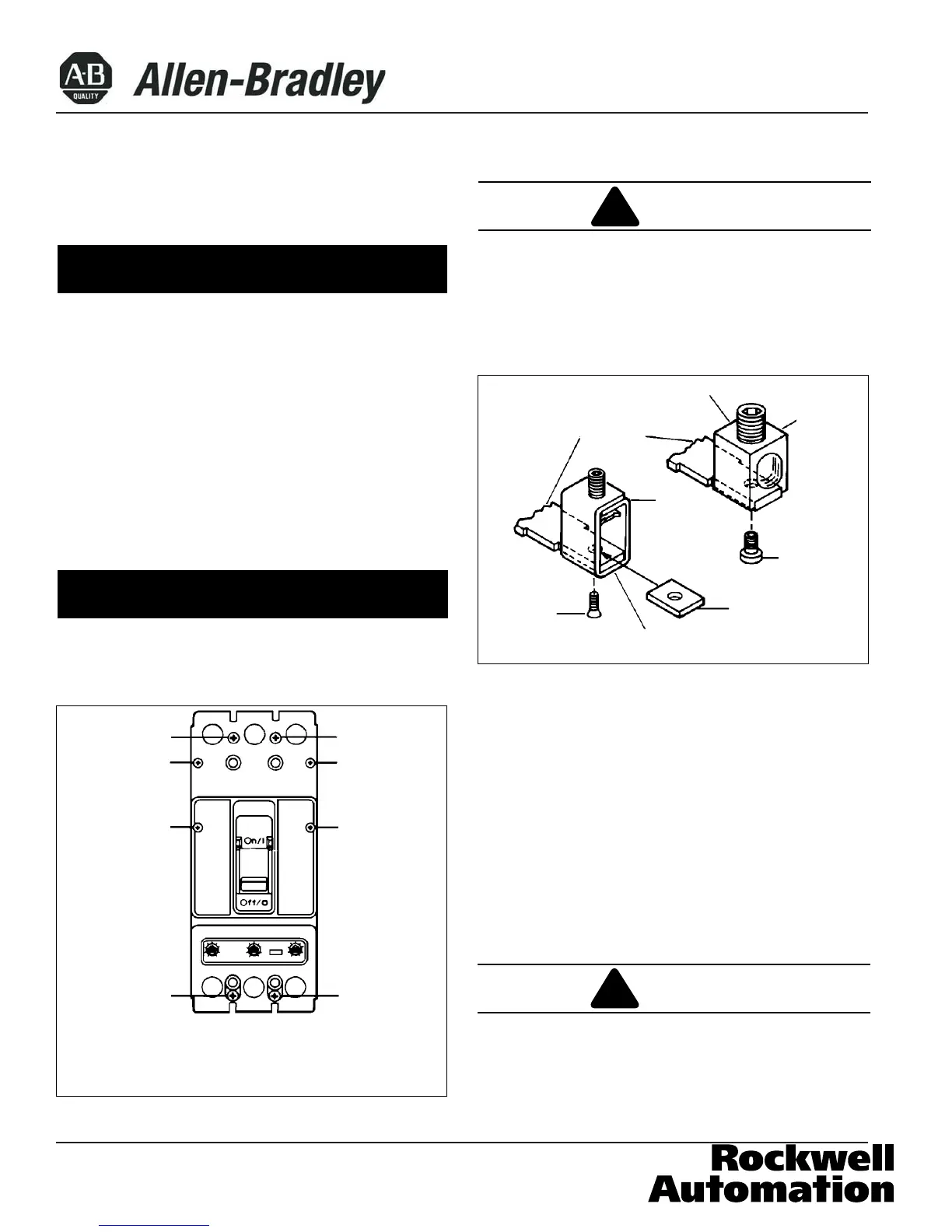
2-5. If not already installed, mount terminals as shown in
Fig. 2-2. When using aluminum body terminal (Catalog
No. TA250KB), secure the terminal to the MCP using a
1/8-inch socket wrench, and torque to 6-8 Ib-ft (8-11
N.m). After mounting the MCP and before installation of
the conductors, check or retighten the terminal mounting
screw through the terminal. Conductor securing screw
must be removed for this check. When using non-alu-
minum body terminal (Catalog No.T250KB), secure the
terminal to the MCP using screw and flat nut. Torque
the screw to 8-lb-in (1 N.m.).
THE VOLTAGES IN ENERGIZED EQUIPMENT CAN
CAUSE DEATH OR SEVERE PERSONAL INJURY.
BEFORE MOUNTING THE MCP IN AN ELECTRICAL
SYSTEM, MAKE SURE THERE IS NO VOLTAGE
PRESENT WHERE WORK IS TO BE PERFORMED.
40752-165(1) Effective March 2008
!
CAUTION
NOTICE
Also
Used
with
4-Pole
Circuit
Breaker
Figure 2-3 Cover Screw Installation Positions
① Screw, .190-32 x 3.13 Inch, Pan-Head, Cross-Recessed
➁ Screw, No. 8 x 1.88 Inch, Pan-Head, Cross-Recessed,
Thread Forming
①
①
①
①
➁
➁
➁
➁
!
WARNING
Figure 2-2 Terminal Installation
TA250KB Terminal
Terminal
Connectors
Collar
Socket
Screw
Collar
Nut
T250KB Terminal
Flat Head
Screw
NOTICE
Page 2
 Loading...