a
CAUTION
PIGTAIL WIRES SHOULD BE FORMED AND ROUTED
TO CLEAR ALL MOVING PARTS WHEN ACCESSORY
IS PROPERLY INSTALLED. PIGTAIL LEADS COULD
BE DAMAGED IF IN CONTACT WITH MOVING
PARTS.
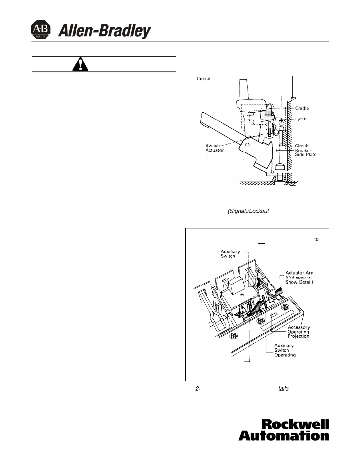
Alarm (Signal)/Lockout Switch Installation
2-12. Insert ASL switch as described in the following
steps:
a.
Put tip of actuator arm through slot in replace-
ment interphase barrier and under cradle. (See
Fig. 2-5.)
b.
Turn ASL switch mounting bracket to line up
with slots in trip unit.
c.
Slide ASL switch mounting bracket into slots
until retaining clip snaps into trip unit. Make
sure ASL switch actuator arm is positioned as
shown in Fig. 2-6. For terminal block assem-
blies, slide terminal block into mounting slot on
side of base as plug-in module is being posi-
tioned.
d.
If required, complete routing of leads to oppo-
site-side through rear wiring trough.
e.
For double ASL switch with pigtail leads, attach
wire marking labels to bundle of three leads for
each switch. (Markers designated 1 and 2 are
provided.)
Accessory Combination Installation
2-l 3. Install accessory combination switch as described
in the following steps:
a.
Put tip of ASL switch actuator arm through slot
in replacement interphase barrier and under
cradle (Fig. 2-7). Make sure ASL switch operat-
ing arm is positioned as shown in Fig. 2-6.
b.
Turn accessory combination mounting bracket
to line up with slots in trip unit.
Trip
Unit
Crrcult
Breaker -- ----
Handle
ASL Switch
Mounting
Bracket
Arm (Must Be
Positioned Under,
And Operated
By the Cradle)
[Interphase Barrier Omitted for Clarity)
Fig. 2-6.
Alarm
(Signal)/Lockout
Switch Actuator Arm
Location
Accessory
Combination Module
-
Position ASL Switch
Actuator Arm Under
Cradle
r
ASL Switch
ASL Switch
six
I
Show
D&ail)
Cradle
1
L
Arm
Slot In Replacement
Interphase Barrier
to
Fig.
2-
7. Accessory Combination Ins talla tion
40752-035(1) Effective 3/02
Page 5
 Loading...