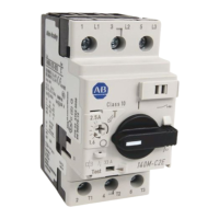
Fig. 2-2.
Recessed
Hole
Location in K-Frame Trip Unit
Note: For an accessory having rear or opposite-side
exiting pigtail leads, thread leads through trough in
side of base before attempting to insert mounting
bracket. Pigtail leads exiting in this manner should
be eased through trough as mounting bracket is
inserted into trip unit retaining slots.
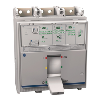
Fig. 2-3. Interphase Barrier Replacement
Rear Exiting Leads
Preferred
Side Exiting Leads
Terminal Block
Opposite-Side
Exiting Leads
Fig. 2-4. Accessory Wiring Options
2-11. Route wiring to meet installation requirements.
(See Fig. 2-4.)
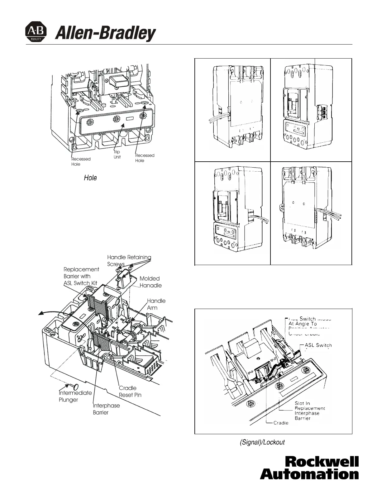
ASL
Switch
Module
Position Actuator Ar
Under Cradle
Actuator Arm
m
Fig. 2-5. Alarm
(Signal)/Lockout
Switch Installation
40752-035(1) Effective 3/02
Page 4
 Loading...