10 FLEX I/O AC Digital Output Modules
Publication 1794-IN103D-EN-P - July 2018
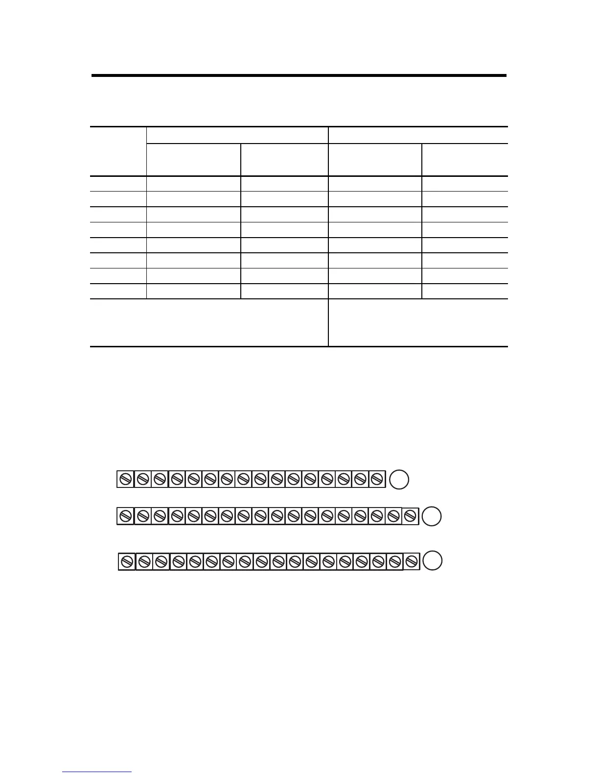
1794-TB2, 1794-TB3, and 1794-TB3S Terminal Base Wiring for 1794-OA8
Wiring Connections for 1794-OA8 and 1794-OA8K
1794-TB2, 1794-TB3, 1794-TB3S 1794-TBN, 1794-TBNF
Output
(1)
Output Terminal Common
Terminal (L2)
(1)
(1)
A-1, 3, 5, 7, 9, 11, 13, and 15 on the 1794-TB2, 1794-TB3, and 1794-TB3S are internally connected in the module to 120V
AC common (L2).
Output Terminal Common
Terminal (L2)
(2)
(2)
C-1, 3, 5, 7, 9, 11, 13, and 15 on the 1794-TBN and 1794-TBNF are internally connected in the module to 120V AC
common (L2).
0 A-0 A-1/B-17 B-0 C-1
1 A-2 A-3/B-19 B-2 C-3
2 A-4 A-5/B-21 B-4 C-5
3 A-6 A-7/B-23 B-6 C-7
4 A-8 A-9/B-25 B-8 C-9
5 A-10 A-11/B-27 B-10 C-11
6 A-12 A-13/B-29 B-12 C-13
7 A-14 A-15/B-31 B-14 C-15
A = Output terminals (Even numbered terminals 0...14)
B = Common terminals
C = Power terminals (C-34 and C-51 on 1794-TB2;
C-34...C-51 on 1794-TB3 and 1794-TB3S)
B = Even numbered output terminals 0...14,
AC common terminals 16 and 33
C = Power terminals C-34 and C-51, and odd
numbered output terminals 1...15
17 18 19 20 21 22 23 24 25 26 27 28 29 30 31 32 33
0 1 2 3 4 5 6 7 8 9 10 11 12 13 14 15
16
35 36 37 38 39 40 41 42 43 44 45 46 47 48 49 50 51
34
Commons
(1794-TB3 shown)
Connect 120V AC common L2 to terminal B-16.
Connect 120V AC power L1 to terminal C-34.
L2 IN L2 OUT
Voltage
A
B
C
(Use B-33 and C-51 for daisy-chaining power to the next terminal base unit.)
L1 IN L1 OUT
(Terminals C-35…C-50 are not present on the 1794-TB2.)
 Loading...


