126 Rockwell Automation Publication 2094-UM001J-EN-P - March 2017
Chapter 5 Connect the Kinetix 6000 Drive System
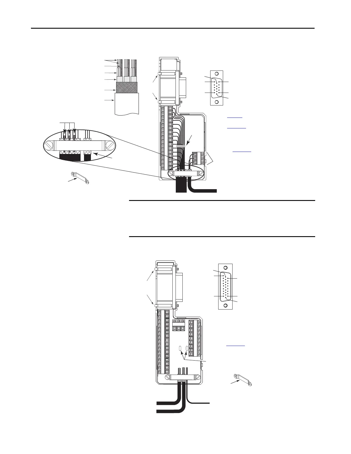
Figure 68 - Wiring (15-pin) Flying-lead Feedback Cable Connections
2090-K6CK-D15MF Connector Kit
Figure 69 - Wiring (26-pin) Flying-lead I/O Cable Connections
2090-K6CK-D26M Connector Kit
Pin 1
Pin 10
Pin 5
Pin 11
Pin 6
Pin 15
1
2
34
5
678
91011121314150
S16
17
15-pin (male) Motor Feedback
Low-profile Connector
Refer to Chapter
4 for feedback signal descriptions.
Refer to Appendix
A for the motor feedback
interconnect diagram for your application.
Pins S, 16, and 17 are included on only 2090-K6CK-D15MF
Low-profile connector kits and used for thermal switch
connections to 1326AB (resolver) motors. After filtering, these
pins connect to MF-11 and MF-6.
Tie
Wrap
Exposed Braid under clamp
1326-CCUT-L-xxx Feedback Cable
Shield Clamp
Thermal Switch Wires
Outer Insulation
Braided Shield
Foil Shield
Wire Insulation
Drain Wire
Bare Wires
Drain wire (only with 1326-CCUT-L-xxx
cable) folded back under clamp.
Turn clamp over to hold
small wires secure.
Mounting
Screws
1326-CCUT-L-xxx
Cable
2090-K6CK-D15MF
Low-profile Connector Kit
Refer to Low Profile Connector Kit Installation Instructions,
publication 2094-IN007
, for connector kit specifications.
IMPORTANT The purpose of the cable shield clamp is to provide a proper ground and
improve system performance, not stress relief.
Clamping the exposed braid under the shield clamp is critical. Turn clamp
over, if necessary, to be sure of a proper ground.
Pin 18
Pin 26
Pin 1
Pin 9
Pin 10
Pin 19
13
14
1516
17
181920
2122
23
S242526S
10
11
12
1
2
34
5
678
9
26-pin (male) I/O
Low Profile Connector
Discrete I/O Wire
Tie Wrap
Slot
Three Conductor
I/O Cables
Turn clamp over to hold
small wires secure.
Mounting
Screws
2090-K6CK-D26M
Low Profile Connector Kit)
Refer to Low Profile Connector Kit Installation Instructions,
publication 2094-IN007
, for connector kit specifications.
 Loading...

