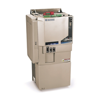
Do you have a question about the Allen-Bradley 2098-DSD-010 and is the answer not in the manual?
Introduction to the manual, covering its scope and audience.
Identifies the intended audience for this manual, focusing on design and wiring.
Details the manual's objective: procedures for mounting, wiring, and connecting.
Outlines customer responsibilities for inspecting and storing equipment upon receipt.
Lists other documents containing additional information on related products.
Explains typographical and formatting conventions used throughout the manual.
Information on obtaining support services, including local and technical assistance.
Lists the topics covered in this chapter related to system installation.
Details regulations and requirements for products sold in the EU.
Provides an overview of system components and typical installation.
Covers system unpacking and minimum mounting requirements before installation.
Specifies enclosure, temperature, and orientation requirements for mounting.
Provides information for sizing cabinets and locating drives within the cabinet.
Guidance on selecting appropriate fuses based on drive input current ratings.
Explains the practice of connecting metal chassis to reduce electromagnetic interference.
Guidelines for mounting filters and resistors to reduce system failures from noise.
Provides procedures for mounting the Ultra3000 drive and its accessories.
Lists topics covered: I/O, encoder, and serial interface connector locations and descriptions.
Describes front panel connectors and their types.
Locates front panel connections for various Ultra3000 drive models.
Details signal descriptions and pin-outs for the CN1 I/O connector.
Provides signal descriptions and pin-outs for the CN2 motor encoder connector.
Describes the analog command input configuration and specifications.
Explains compatibility with different encoder types and feedback signals.
Details the serial port, communication standards, and baud rates supported.
Lists procedures for wiring and making cable connections for the Ultra3000.
Contains basic wiring information and practices for the Ultra3000.
Provides examples of single-phase and three-phase input power wiring.
Covers chassis ground configurations and bonding practices for safety.
Details wire size and terminal block torque values for power connections.
Provides procedures for wiring the AC input power to the Ultra3000 drive.
Details wiring procedures for motor power, brake connections, and cable shields.
Assumes setup is complete and guides connection of fiber-optic cables.
Covers planning and connecting a DeviceNet network for optimal communication.
Outlines maintenance and troubleshooting activities for the Ultra3000.
Lists essential safety precautions to follow when troubleshooting the Ultra3000 drive.
Provides guidance on identifying problems, causes, and actions for resolution.
Lists problematic symptoms and assigned error codes for troubleshooting.
Guides troubleshooting of SERCOS Module Status and Network Status LEDs.
Guides troubleshooting of DeviceNet Module and Network Status LEDs.
Lists topics covered: Certifications, Power Specifications, General Specifications, and Dimensions.
Details UL listing and CE marking for the Ultra3000 product.
Provides detailed power specifications for 230V and 460V Ultra3000 drives.
Lists physical, environmental, control, and I/O specifications for Ultra3000 drives.
Details encoder types, input frequency, and commutation startup specifications.
Lists compatible AC line filters and their specifications for Ultra3000 drives.
Provides diagrams showing dimensions and mounting hole locations for Ultra3000 drives.
Lists the interconnect diagrams included in this appendix.
Provides notes applicable to power, drive/motor, and shunt interconnect diagrams.
Illustrates typical power wiring configurations for Ultra3000 systems.
Shows interconnect diagrams for active and passive shunt modules.
Illustrates connections between Ultra3000 and various motor series.
Provides an example configuration for controlling a motor brake.
Lists catalog numbers and descriptions for Ultra3000 drives and accessories.
Identifies catalog numbers for Ultra3000 230V and 460V drives.
Lists compatible AC Line Filters and their catalog numbers.
Identifies catalog numbers for various motor power cables.
Lists catalog numbers for motor feedback cables for different motor series.
Provides catalog numbers for motor end connector kits.
Lists catalog numbers for breakout board kits.
| Model | 2098-DSD-010 |
|---|---|
| Product Type | Servo Drive |
| Power Rating | 1.0 kW |
| Input Voltage | 200-240 VAC |
| Output Current | 5.0 A |
| Communication Protocol | EtherNet/IP |
| Voltage | 200-240 VAC |
| Continuous Output Current | 5.0 A |
| Communication | EtherNet/IP |
| Protection Class | IP20 |
| Type | Servo Drive |
| Feedback | Yes |


 Loading...