Publication 2098-IN003E-EN-P — April 2004
Ultra3000 Connector Data 2-47
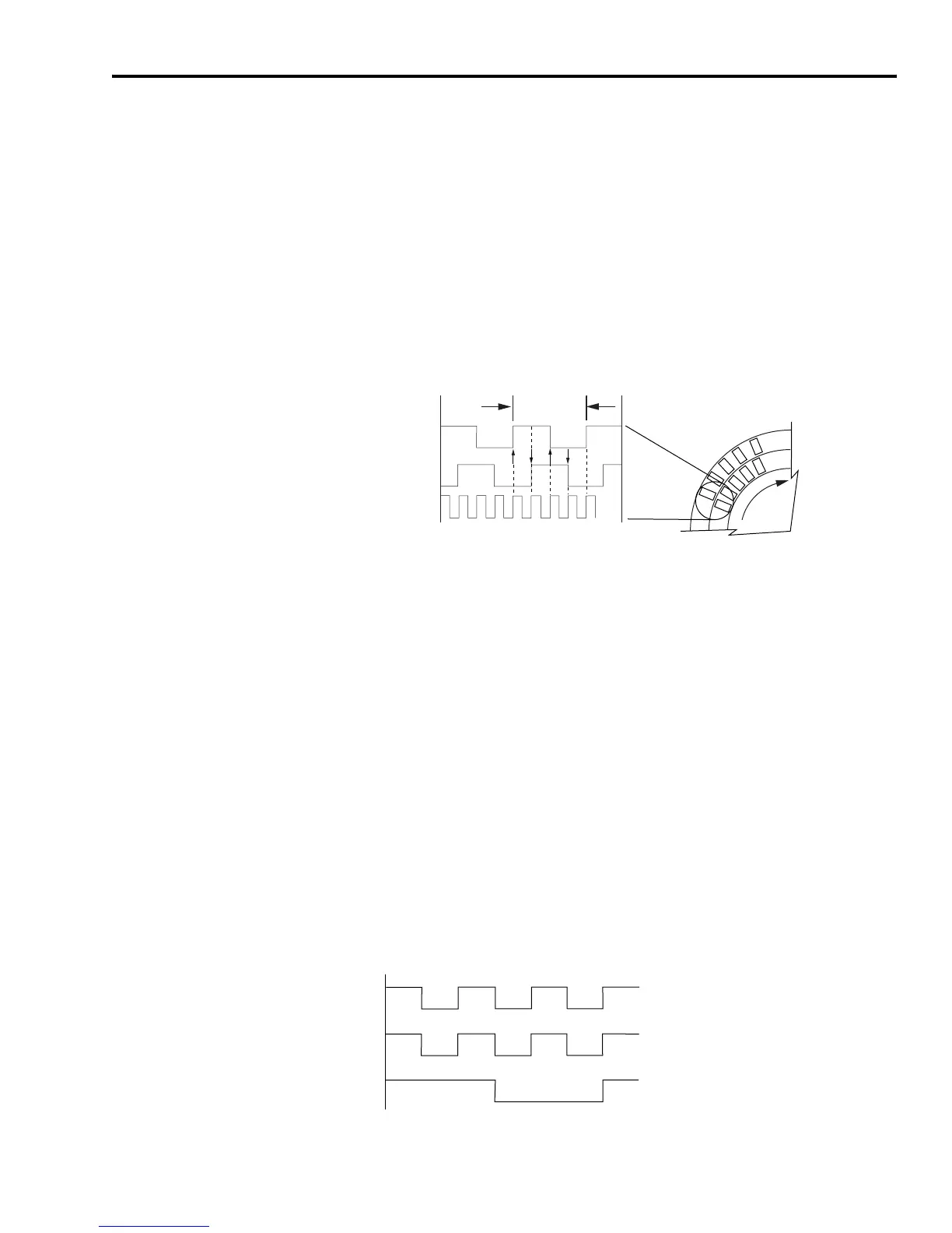
Incremental Encoder Output
Incremental encoder counts are generated in the drive by counting the
(high to low and low to high) transitions of the incoming A and B
encoder signals. In Figure 2.49 the channel A signal has two
transitions, as does the channel B signal, which results in x4
interpolation (4 transitions/line equals 4 counts/line). So, for example,
typical 2000 line/rev encoder output becomes 8000 counts/rev in the
drive. Counts are not directly available at the encoder outputs, only
the A quad B representation.
Figure 2.49
Incremental Encoder Counts
The incremental buffered outputs available from the drive (CN1-16
through -21) are software selectable as follows:
• Buffered Outputs are a filtered representation of the original
incoming encoder (CN2) signals. Buffered outputs have the same
number of cycles/rev as found on CN2.
• Interpolated Outputs are the same as buffered outputs when
using an incremental encoder. The only interpolation performed
on an A quad B signal is the drive’s internal counting of transitions
(4 counts/line). Because counts are not available outside the drive,
selecting this in software is the same as selecting buffered (as
described above).
• Divided Outputs are the same as buffered outputs, except when
divided is selected in the software, the lines/rev are then reduced
by the value of the divisor chosen in the software (as shown in the
figure below).
Figure 2.50
Incremental Encoder Divided
One Cycle
Channel A
Channel B
Counts
B
A
CW
CN2-1
CN1-10
CN1-16
Signal A+ from Incremental Encoder
Unbuffered Signal A+ Output from Drive
Divided (by two) Signal A+ Buffered Output from Drive

 Loading...

