FLEX I/O Digital Input and Output Modules w/ Diagnostics 15
Publication 1794-IN096C-EN-P - August 2015
Configuring Your Module
Configuring Your 1794-IB16D Input Module
Configure your input module by setting bits in the configuration word (word 3). This
module is compatible with the Remote I/O network (with 1794-ASB series E or later),
DeviceNet network, and the ControlNet network. (Note: You must use the Module
Connection when used in a ControlNet system.)
Setting the Input Filter Time
To set the input filter time, set the associated bits in the output image (complementary
word) for the module.
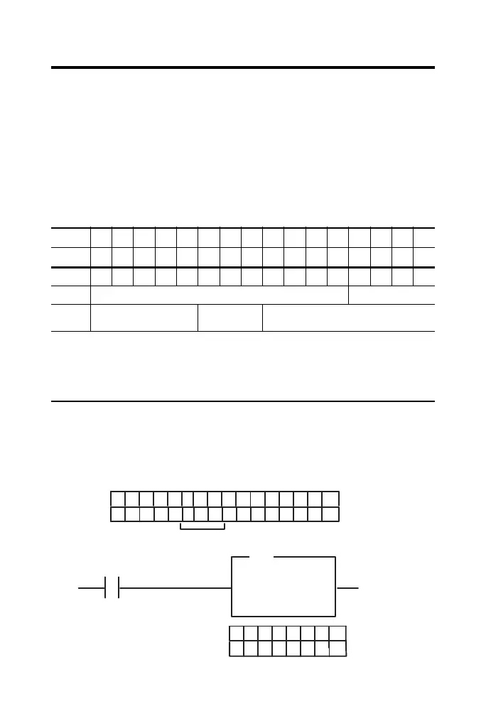
Image Table Memory Map for the 1794-IB16D Module
Dec 1514131211109876543210
Oct 17161514131211107 6 5 4 3 2 1 0
Read 1 I15I14I13I12I11I10I9I8I7I6I5I4I3I2I1I0
Read 2 Read Diagnostic Status
Write 3 Not Used Input Filter FT
0...15
Not Used
Where
Diagnostic
Status
I = Input status
FT = Filter Time
Bit 00 = Module error;
Bit 01 = External power reverse polarity error;
Bit 02 = Sensor power short error;
Bit 03 = Sensor power open wire error
15 14 13 12 11 10 9 8 7 6 5 4 3 2 1 0
1794-IB16D
FT = 0-15
FLL
I:000
00
Fill File
Source
Destination
Length
#O:010
1
Write FT to complement
of input module.
Write filter time on system startup.
O:010
Dec.
12 11 10 9 8 7 6 5
1
= 5 Octal or 5 Decimal
01
1794-IB16D
 Loading...


