1 Publication 1760-GR001C-EN-P - April 2005
Chapter
3
Pico Interface Socket
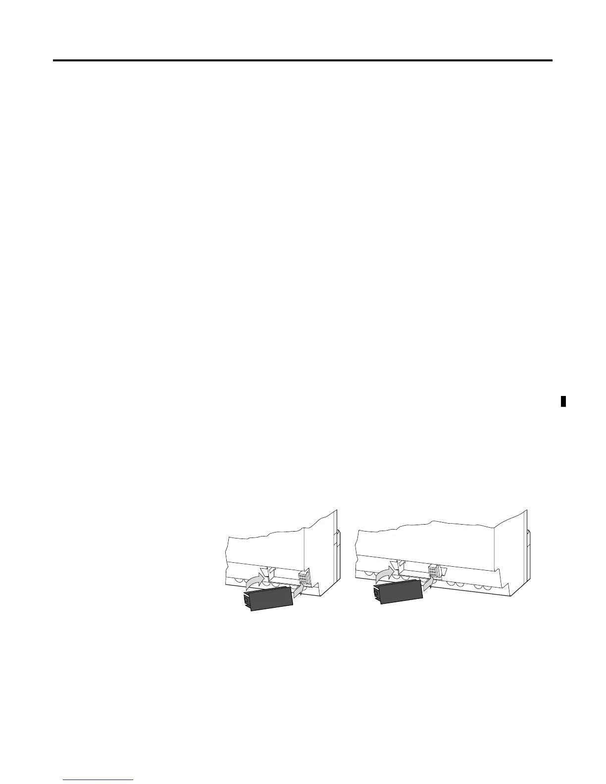
The Pico interface socket, which is beneath a protective cap, accepts
the optional Pico memory module, or connects Pico to a PC using the
optional PC interface cable and the PicoSoft software. This allows you
to copy the circuit diagrams to and from the PC and/or memory
module.
Memory Module
Memory modules are available as an optional accessory. Each memory
module can store a single Pico circuit diagram. Information stored on
the memory module is non-volatile (the information is not lost when
the power is turned off). The memory module can be used to make a
backup copy of a program and/or to transfer it to another Pico
controller.
Each memory module can hold one Pico program, up to 32K.
Each memory module stores:
• the circuit diagram
• all parameter settings of the circuit diagram
• system settings
1760-MM1 for all 1760-L12xxx
controllers
1760-MM2 for the 1760-L18xxx
controllers
 Loading...