Enhanced PLC-5 Programmable Controller Firmware Upgrade2
Publication17855.13 April 1996
Follow these steps to upgrade the processor firmware.
1
Save
processor memory using the programming software.
2
Remove the battery cover and disconnect the battery
.
3
Skip this step if you have a PLC5/1
1 or 5/20 processor
.
Remove the phillips head screw near the channel 1B LED and
gently remove the channel 1 communication plug. Be aware
that the memory grounding clip may move or drop off from the
cover mounting tab.
4
Skip this step if you have a PLC5/1
1 or 5/20 processor
.
Remove the lug nuts that hold the serial channel to the metal
face plate. These lug nuts are located on the exposed circuit
board for PLC5/40 and 5/60 processors.
5
Remove the four screws that hold the right side plastic cover
.
6
Remove the washers and two remaining screws located in the
middle of the exposed circuit board.
Separate the two processor boards by pulling the exposed circuit
board at the backplane edge connector away from the metal cover
as you would open a book. Notice the direction in which the battery
cable is wrapped around the nearby standof
f to prevent obstruction
of the dip switch. After you separate the boards, pull the battery cable
through the battery housing (still attached to the circuit board.)
8
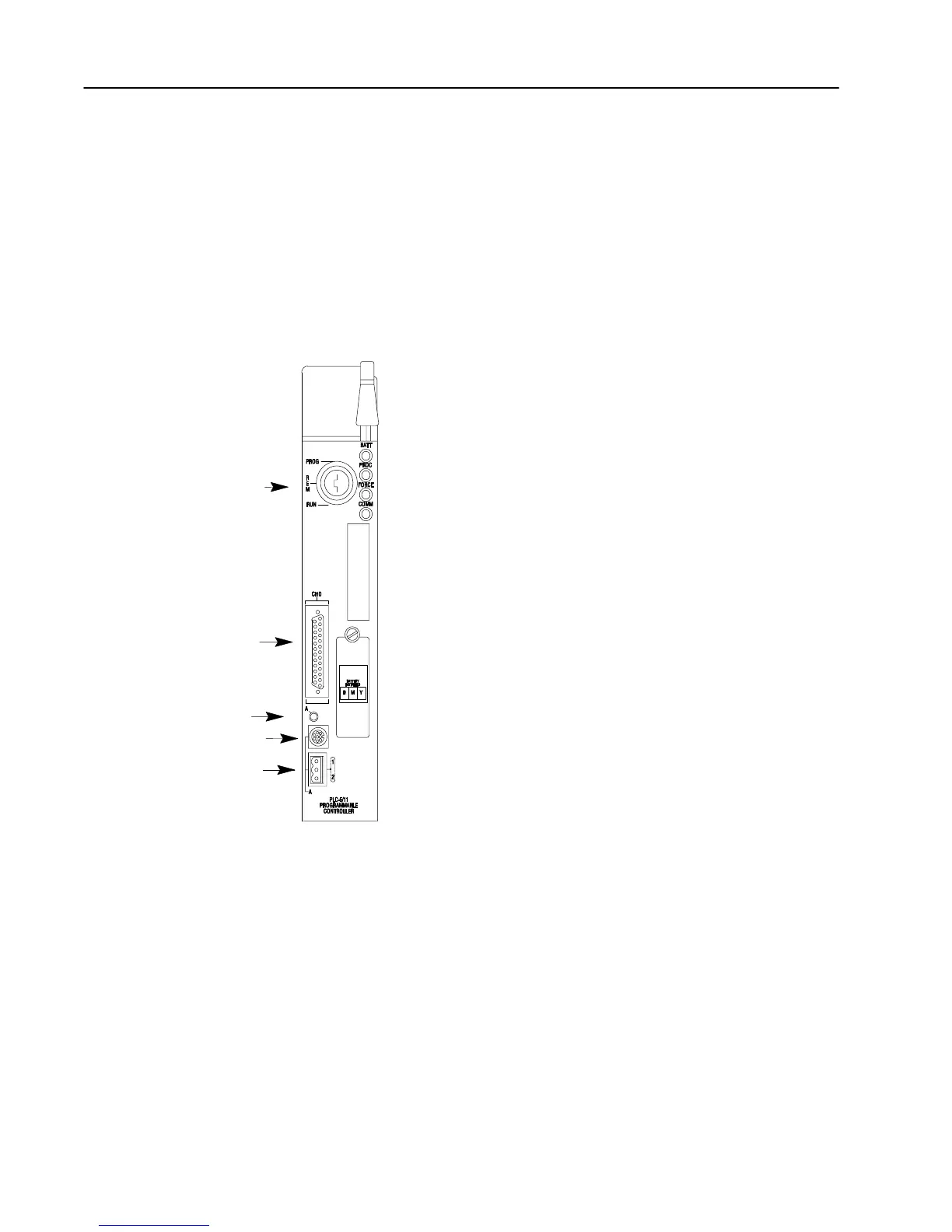
Disconnect the wires leading from the keyswitch to the stake pins on
the exposed circuit board.
keyswitch;
selects processor mode
channel 1A communication
port;
8pin miniDIN, DH+ programming
terminal connection
channel 1A status indicator
channel 0 serial port
7
To Upgrade the Processor
Firmware ...
 Loading...


