EasyManuals Logo

Allen-Bradley PowerFlex 20-750-S1 User Manual

Allen-Bradley PowerFlex 20-750-S1
302 pages
To Next Page IconTo Next Page
To Previous Page IconTo Previous Page
Page #199 background imageLoading...
Page #199 background image
Rockwell Automation Publication 750-IN001O-EN-P - October 2014 199
Power Wiring Chapter 4
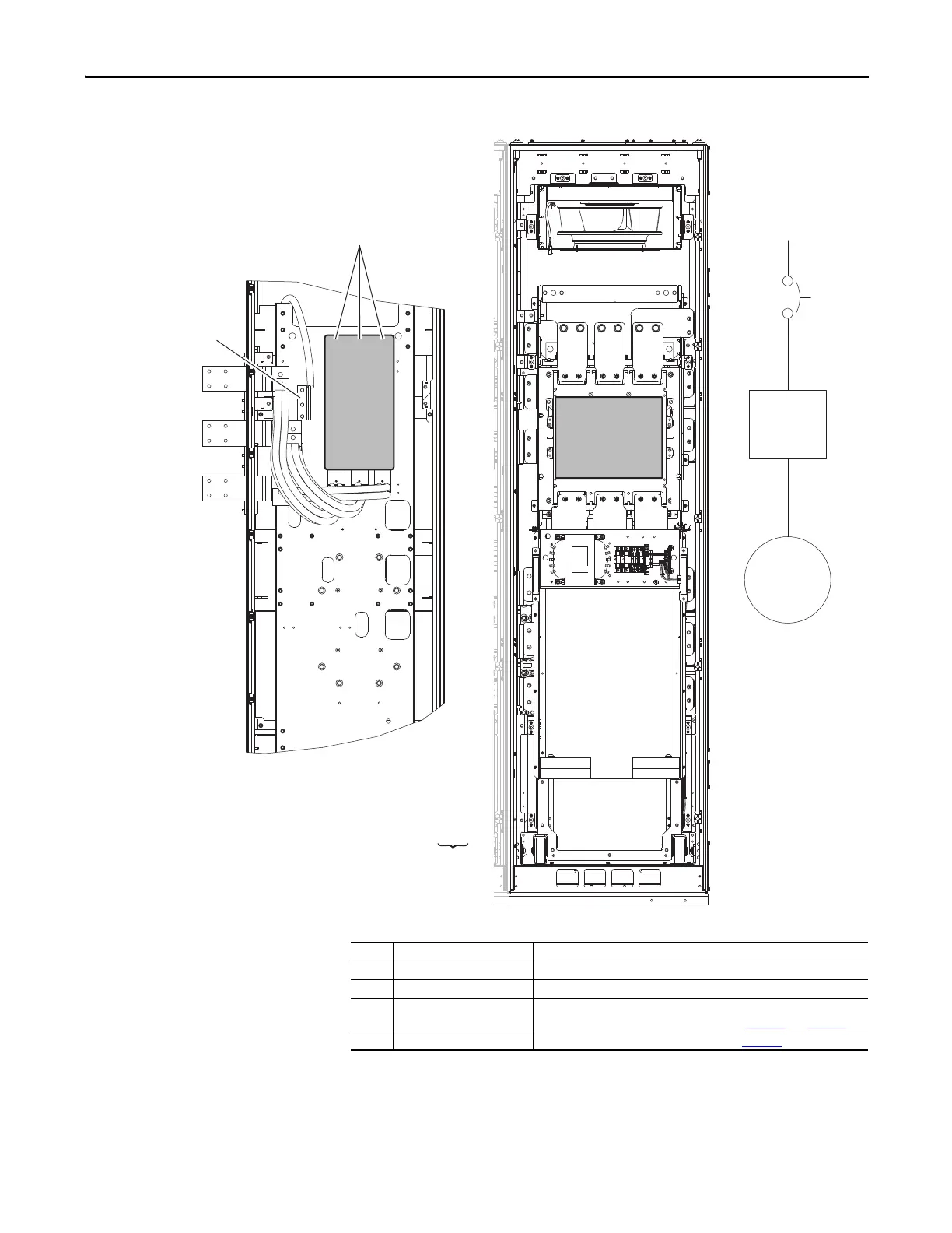
Figure 103 - Option P3 or P5 Disconnect
U / T1
V / T2
W / T3
Drive
Motor
P3 or P5
Floor Mount Frame 8 Floor Mount Frame 9
No. Name Description
R/L1, S/L2, T/L3 Three-phase input power connection.
PE Three-phase input ground.
R/L1, S/L2, T/L3 Three-phase input power for frame 9 drives lands on the horizontal bus bars
behind the cabinet options rollout assembly. See page 164
and page 165.
U/T1, V/T2, W/T3 Motor connection made at drive power bus. See page 156
.

Table of Contents

Questions and Answers:

Question and Answer IconNeed help?

Do you have a question about the Allen-Bradley PowerFlex 20-750-S1 and is the answer not in the manual?

Allen-Bradley PowerFlex 20-750-S1 Specifications

General IconGeneral
BrandAllen-Bradley
ModelPowerFlex 20-750-S1
CategoryController
LanguageEnglish

Related product manuals